
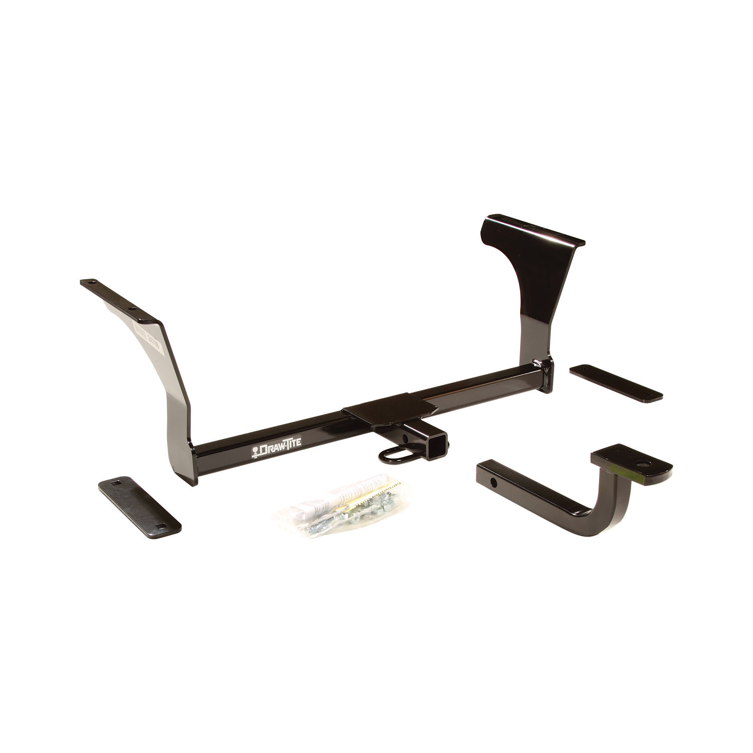
2009-2014 Nissan Maxima Draw-tite Class 1 Trailer Hitch, 1-1/4 Inch Square Receiver Bundle w/ Plug-n-Play T-One Wiring HarnessDraw-titeOriginal price was $342.50. Current price is $305.50.Out of Stock
View productOur in-house experts typically reply within one business day.

Draw-tite
Verify Fitment
Select your vehicle to confirm this part fits.
2007 - 2017 Nissan Maxima
Confirmed to Fit



Always the correct part
We know our products
Quality Products
Free Shipping!
Always the correct part
We know our products
Quality Products
Free Shipping!
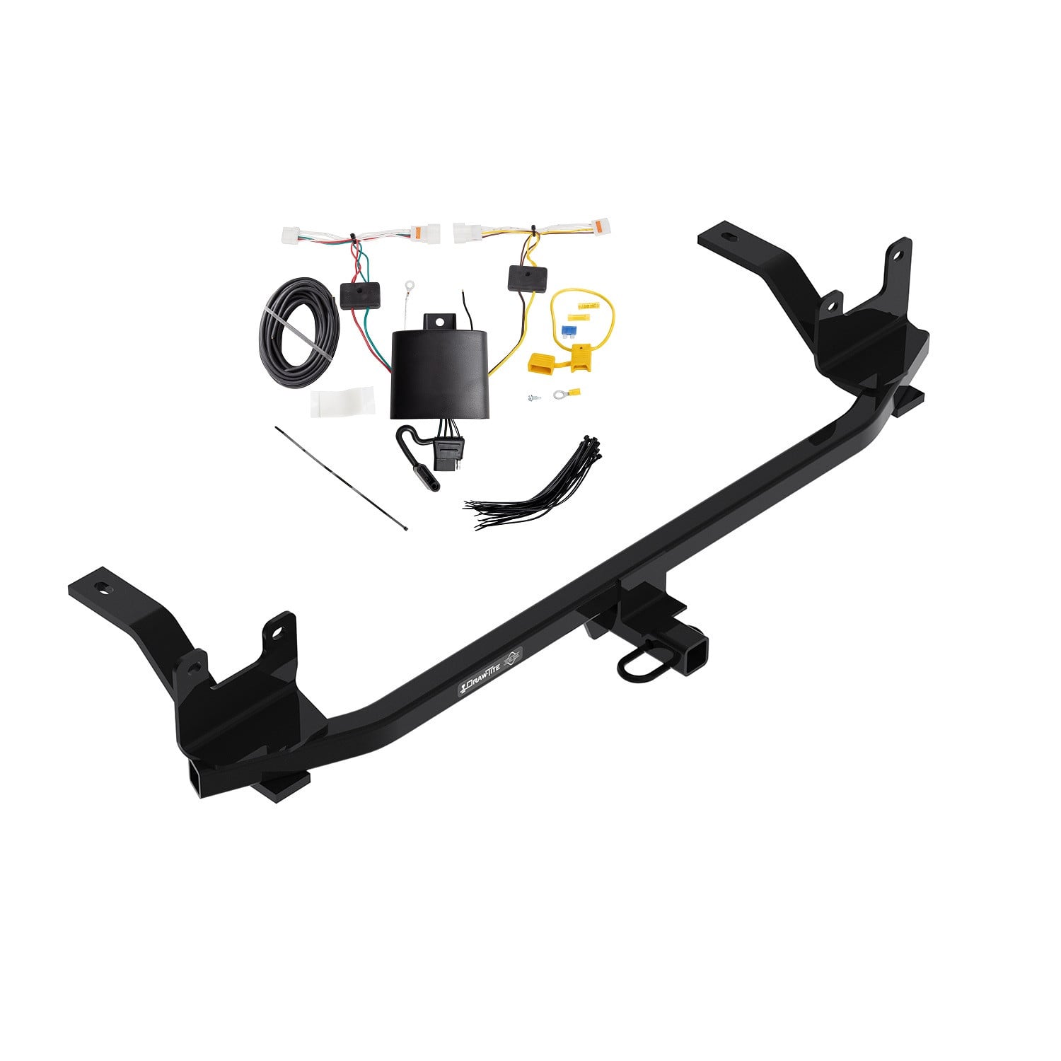
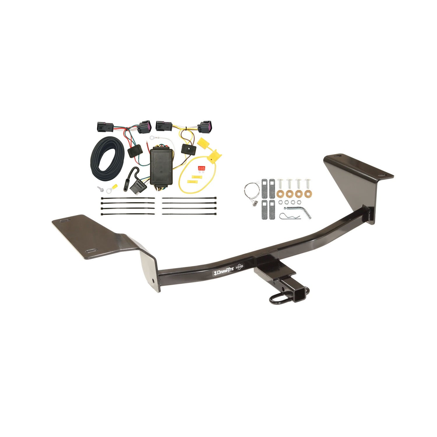
These dependable custom hitches are manufactured for 2007-2023 Nissan Altima, 2009-2022 Nissan Maxima and attach to your vehicle?s frame or bumper for a sleek, clean appearance. Each hitch also has a 1-1/4 inch square receiver tube opening so you can easily attach accessories like a bike rack or cargo carrier, or a utility trailer. DRAW-TITE Class 1 custom trailer hitches come complete with all the mounting hardware needed for installation and are backed by a nationwide lifetime limited warranty. So, whether you are headed out to the campground and need a place for the cooler, taking the bikes to hit the trails in the park, or you are tackling a DIY project (maybe some landscaping or a home repair), choose DRAW-TITE and travel with confidence knowing your setup is connected with the security only DRAW-TITE can provide. DRAW-TITE: North America?s Favorite Hitch.

Draw-Tite has designed custom-fit trailer hitches since 1946 and is one of North America's most widely fitted hitch brands. Receiver hitches use solid all-welded construction and low-profile designs that follow modern vehicle contours, install with minimal bumper cutting or drilling, meet or exceed V5 CSA and SAE J684 standards, and carry a limited lifetime warranty.
Draw-Tite has been leading custom-fit trailer hitch design and engineering since its founding in 1946, and it remains one of the most widely fitted hitch brands in North America. The company's stated approach is straightforward: every hitch is tested rigorously so that it performs well beyond published industry standards, a philosophy it markets as Tested Tough. It sits within the Horizon Global towing group alongside Reese, Fulton, Bulldog, Tekonsha, Bargman and Wesbar.
Custom fit is the defining characteristic. Rather than adapting a universal design, Draw-Tite engineers a trailer hitch for a specific make, model and model year, so it bolts to existing frame locations with minimal bumper cutting or drilling. Low-profile designs follow the rear contours and aerodynamic styling of modern vehicles, which matters more than it once did now that rear fascias are shaped and sensor-equipped. Construction is solid all-welded steel for maximum strength, and every hitch meets or exceeds V5 CSA and SAE J684 standards and is backed by a nationwide limited lifetime warranty.
The range spans receiver sizes and classes to suit different loads, from 1-1/4 inch receivers for bike racks, cargo carriers and light trailers up through 2 inch receivers for heavier towing. Front mount hitches add a receiver at the front of the vehicle for winch mounts, snow plows, spare carriers and precise trailer positioning.
The Hidden Hitch series takes concealment further by mounting behind the vehicle's rear fascia, so the vehicle keeps its factory appearance until a removable receiver is fitted. Each is custom designed per make and model for a no-drill installation that does not compromise ground clearance, rated for up to 3,500 pounds gross trailer weight and 350 pounds tongue weight. Matching plug-and-play wiring completes the towing system.
Experts available to answer your questions
Call 888-634-94941 compatible vehicles
| Year | Make & Model | Notes |
|---|---|---|
| 2007 - 2017 | Nissan Maxima | — |
The 2016-2023 Nissan Maxima Draw-Tite Class 1 Trailer Hitch, 1-1/4 Inch Square Receiver Bundle w/ Plug-n-Play T-One Wiring Harness (Part #DTB24796-118676) fits the following vehicles: 2007-2017 Nissan Maxima. Always verify your specific year, make, and model before ordering.
The 2016-2023 Nissan Maxima Draw-Tite Class 1 Trailer Hitch, 1-1/4 Inch Square Receiver Bundle w/ Plug-n-Play T-One Wiring Harness (Part #DTB24796-118676) fits 2007-2017 Nissan Maxima models. The 2017 model year is the last year covered by this part number. For newer models, check for an updated version.
Yes, the 2016-2023 Nissan Maxima Draw-Tite Class 1 Trailer Hitch, 1-1/4 Inch Square Receiver Bundle w/ Plug-n-Play T-One Wiring Harness (Part #DTB24796-118676) is designed to fit the 2007-2017 Nissan Maxima.
The 2016-2023 Nissan Maxima Draw-Tite Class 1 Trailer Hitch, 1-1/4 Inch Square Receiver Bundle w/ Plug-n-Play T-One Wiring Harness (Part #DTB24796-118676) Refer to the included instructions for installation details. Basic hand tools are typically all you need.
This hitch (part numbers 60873, 24796, 77168) is designed for Nissan Altima and Nissan Maxima models from 2007 and later. The installation method varies by year: 2007–2011 models disconnect the exhaust at the flange, while 2012 and later models disconnect at the lap joint. Confirm your vehicle year matches before purchasing.
The maximum gross trailer weight is 2000 LB (908 kg), and the maximum tongue weight is 200 LB (90.8 kg). Do not exceed the lower of the towing vehicle manufacturer's rating or these limits.
You will need wrenches in sizes 11/16", 5/8", and 16 mm, a 7/16" drill bit, a torque wrench (to tighten fasteners to 50 LB-FT), and sealant. A center punch is also needed to mark hole locations.
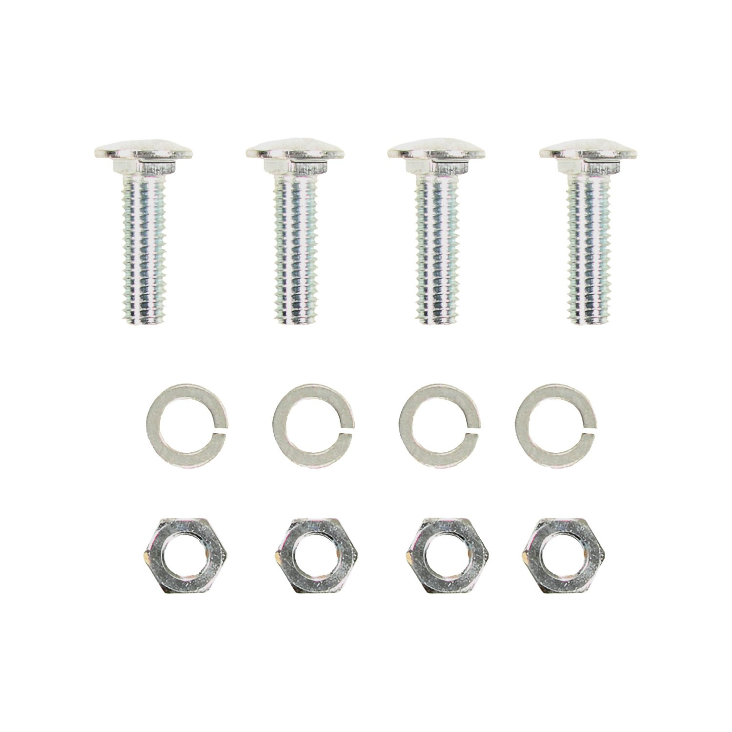
The hitch includes 4 carriage bolts (7/16-14 X 1.50 GR5), 4 nuts (7/16-14), and 4 lock washers. These fasteners are tightened to 50 LB-FT. A separate fastener kit (24796F) is available if additional fasteners are needed.
Yes, drilling is required. You must drill two 7/16" holes through the trunk pan on each side (4 holes total) at center-punched locations. The manual specifies that you should check hole alignment under the vehicle and remove burrs after drilling. Do not use a torch to cut holes.
Yes, the heat shield must be gently bent toward the frame rail during installation to expose the area between the frame rail and wheel well (Step 4). After the hitch is installed and fastened, the heat shield is gently bent back into position (Step 10). The manual does not indicate whether this bending causes permanent deformation.
Yes, the exhaust must be disconnected. The method depends on your vehicle year: 2007–2011 models disconnect at the flange on both sides, while 2012 and later models disconnect at the lap joint on both sides. Keep all fasteners for reassembly. The exhaust is then pushed toward the rear and off the rubber isolator.
1. Mark and center-punch the two hole locations on each side using the hitch as a template. 2. Lower the hitch and drill 7/16" holes through the trunk pan. 3. Position the plate over the holes inside the trunk and insert carriage bolts through the plate and trunk pan. 4. Raise the hitch over the carriage bolts and install lock washers and hex nuts. 5. Tighten all 7/16-14 GR5 fasteners to 50 LB-FT using a torque wrench.
The hitch should be raised into position between the frame rails and the spare tire wheel well, with the rear edge of the side bracket aligned flush against the bulkhead. Be careful not to scratch the fascia during positioning. Check the hitch location on the vehicle before marking and drilling holes.
No. The manual explicitly states not to install fasteners over carpet. Position the plate over the holes inside the trunk on the bare trunk pan before inserting the carriage bolts.
All 7/16-14 GR5 fasteners must be tightened to 50 LB-FT (68 N·M) using a torque wrench. This applies to all four carriage bolts with their corresponding lock washers and nuts.
The holes must be 7/16" in diameter. Two holes are drilled on each side of the vehicle (4 holes total) through the trunk pan at the center-punched locations marked using the hitch as a template.
The drawbar must be used in the RISE position only. Do not use it in any other position.
Observe safety precautions when working beneath the vehicle and wear eye protection. Do not cut access or attachment holes with a torch. If the hitch is removed, plug all holes in the trunk pan or other body panels to prevent entry of water and exhaust fumes. A damaged hitch or ball must be removed and replaced immediately.
After installation, apply sealant at the bolt attachments inside the spare tire well to prevent water and exhaust fumes from entering the vehicle interior. Replace the carpeting, fiber board, and storage bin tray (if present). Check the hitch frequently to ensure all fasteners and the ball are properly tightened.
Check the hitch frequently to ensure all fasteners and the ball are properly tightened. The manual does not specify an exact interval, but regular inspection is recommended to maintain safe operation.
If the hitch is removed, plug all holes in the trunk pan or other body panels to prevent entry of water and exhaust fumes into the vehicle interior.
The drawbar kit is part number 3594 and is sold separately.
The wiring access locations are PC3 and PC4. Consult the vehicle's electrical documentation or a qualified installer for the exact location of these access points on your specific model.
Maximum gross trailer weight: 2000 LB (908 kg). Maximum tongue weight: 200 LB (90.8 kg). Do not exceed the lower of the towing vehicle manufacturer's rating or these limits.
Wrenches (11/16", 5/8", 16 mm), 7/16" drill bit, torque wrench, center punch, and sealant.
Yes. You must drill four 7/16" holes through the trunk pan (two on each side). Do not use a torch to cut holes.
Yes. 2007–2011 models: disconnect at the flange on both sides. 2012 and later: disconnect at the lap joint on both sides. Keep all fasteners for reassembly.
All 7/16-14 GR5 fasteners must be tightened to 50 LB-FT (68 N·M) using a torque wrench.
The drawbar must be used in the RISE position only.
Apply sealant at bolt attachments inside the spare tire well. Check the hitch frequently to ensure all fasteners and the ball are properly tightened.
Yes, this T-Connector is designed for the Nissan Maxima. The manual does not specify model year range, so confirm your vehicle year with the manufacturer or retailer before purchase.
You need: trim panel remover, drill with 3/32" bit, Phillips head screwdriver, and test probe.
Yes. You must disconnect the vehicle's negative (-) battery cable before connecting the fuse holder to the positive battery terminal in step 7, and reconnect it after installing the 15 amp fuse in step 8.
Yes. You must drill a 3/32" hole to secure the white ground wire using the eyelet and screw provided. You must verify what is behind the surface before drilling to avoid damage to the vehicle or personal injury, and do not drill into exposed surfaces.
Install a 15 amp fuse into the yellow fuse holder provided.
Do not exceed the lower of your towing manufacturer's rating or: maximum stop/turn light 2 per side (4.2 amps) or maximum tail lights (7.5 amps). Overloading the circuit can cause fires.
Test and verify the installation with a test light or trailer. For the initial test, reset the vehicle electrical system by temporarily removing the key from the ignition. All connections must be complete for the T-Connector to function properly.
The T-One® T-Connector is a trailer wiring harness that connects to your vehicle's taillight wiring to provide power for trailer lights. It uses a black box module and connects to both the driver and passenger side taillight connectors via T-shaped connector ends with yellow and green wires.
The kit includes: two T-Connector ends (one with yellow wire, one with green wire), a black box module, a white ground wire with eyelet and screw, a 12 gauge black wire, a yellow fuse holder with 15 amp fuse, yellow butt connectors, cable ties, and a 4-flat connector for storage in the trunk when not in use.
The T-Connector is designed to connect to your vehicle's taillight wiring harness. The taillight wiring harness must have a connection point on both driver and passenger sides that matches the ends of the T-Connector. If your vehicle's connectors do not match, the T-Connector will not fit. Verify compatibility before purchase.
Yes. You must open the trunk, temporarily remove the rear threshold plate, and partially remove the felt trunk liner behind the taillights to access the taillight wiring harness. You will reinstall the carpet and panels after installation, being careful not to cut or pinch the wires.
Locate the vehicle's taillight wiring harness on both driver and passenger sides. Separate the connectors carefully without breaking the locking tabs. Clean all connector surfaces to remove dirt before inserting the T-Connector ends.
Insert the T-Connector end with the yellow wire on the driver's side. Insert it between the vehicle's taillight wiring connectors and lock into place, ensuring the locking tabs are fully engaged and not damaged.
Route the T-Connector end with the green wire to the passenger's side behind the panels and along the threshold. Insert it between the vehicle's taillight wiring connectors and lock into place, ensuring the locking tabs are fully engaged and not damaged.
Locate a suitable grounding point near the connector. Clean dirt and rustproofing from the area. Drill a 3/32" hole and secure the white ground wire using the eyelet and screw provided. Before drilling, verify what is behind the surface to avoid damage to the vehicle or personal injury, and do not drill into exposed surfaces.
From inside the vehicle, connect the black 12 gauge wire and the black wire from the T-Connector black box using the supplied yellow butt connector. Route the black wire either through a grommet and along the exterior frame, or follow the existing wiring along the thresholds into the engine compartment up to the battery. Avoid areas that may pinch or break the wire. If routing through a grommet and along the exterior, avoid hot pipes, heat shields, the fuel tank, or any other points that may pinch or break the wire.
Disconnect the vehicle's negative (-) battery cable. Remove the fuse from the yellow fuse holder provided. Cut the fuse holder wire and attach the ring terminal to the vehicle's positive (+) battery cable. Connect the other end of the fuse holder to the black 12 gauge wire using the supplied yellow butt connector. Reconnect the negative battery cable and install the 15 amp fuse into the fuse holder.
The T-Connector uses yellow wire on the driver's side connector, green wire on the passenger's side connector, white wire for the ground connection, and black wire for the battery connection. The yellow fuse holder and yellow butt connectors are also part of the electrical system.
Locate a flat surface in an out-of-the-way place inside the vehicle and mount the black box module to prevent damage or rattling.
Secure the remainder of the T-Connector harness with the cable ties provided to prevent damage or rattling. Be careful to avoid any areas that would pinch, cut, or melt the wire.
Store the 4-flat connector in the trunk area when the T-Connector is not in use.
Wear safety glasses and use all safety precautions during installation. Before drilling, verify what is behind any surface to avoid damage to the vehicle or personal injury. Do not drill into exposed surfaces. When routing wires, avoid hot pipes, heat shields, the fuel tank, or any other points that may pinch or break the wire. Read and follow all warnings and cautions printed on the vehicle's battery. Do not exceed the circuit load limits to prevent fires.
Be careful not to damage the locking tabs when inserting the T-Connector ends into the vehicle's taillight connectors. The manual does not provide instructions for replacing damaged locking tabs. If tabs are damaged, contact the manufacturer for a replacement connector.
The yellow butt connectors are used to join wires together. One is used to connect the black 12 gauge wire and the black wire from the T-Connector black box (step 6). Another is used to connect the fuse holder to the black 12 gauge wire (step 7).
Verify that all connections are complete. Test and verify the installation with a test light or trailer. For the initial test, reset the vehicle electrical system by temporarily removing the key from the ignition. Check that the 15 amp fuse is installed in the fuse holder and is not blown. Ensure the black box module is properly mounted and all cable ties are secure. Verify that the T-Connector ends are fully inserted into the vehicle's taillight connectors with locking tabs in place.
Ensure the connector surfaces are clean and free of dirt. Verify that the T-Connector ends match the vehicle's taillight connector ends. Do not force the connectors; they should insert smoothly. If the connectors do not match or will not insert, the T-Connector may not be compatible with your vehicle. Contact the manufacturer or retailer for compatibility verification.
The locking tabs are critical for securing the T-Connector ends to the vehicle's taillight connectors. If the tabs are damaged, the connectors may not stay in place and the T-Connector will not function properly. The manual does not provide a repair procedure. Contact the manufacturer for a replacement connector.
A blown fuse indicates an electrical overload or short circuit. Verify that you are not exceeding the circuit load limits: maximum stop/turn light 2 per side (4.2 amps) or maximum tail lights (7.5 amps). Do not exceed the lower of your towing manufacturer's rating or these limits. Check all wire connections for loose or damaged wires that could cause a short. If the fuse continues to blow, there may be a wiring fault. Contact the manufacturer or a qualified technician.
Mount the black box module on a flat surface in an out-of-the-way place inside the vehicle. Secure the remainder of the harness with the cable ties provided to prevent damage or rattling. Ensure the module is mounted firmly and the cable ties are tight.


Total for 4 items:
$150.58
On Sale Today
Original price was $342.50. Current price is $298.09.You save $44.41 (13%)
Free Shipping
Ships free on all orders
 Authorized Dealer

FREE ShippingFREE SHIPPING
Estimated delivery Tue, Sep 22 - Fri, Sep 25
Order before 2 PM EST Monday–Friday for same-day processing
Guaranteed safe & secure checkout
No reviews have been added for this product.