
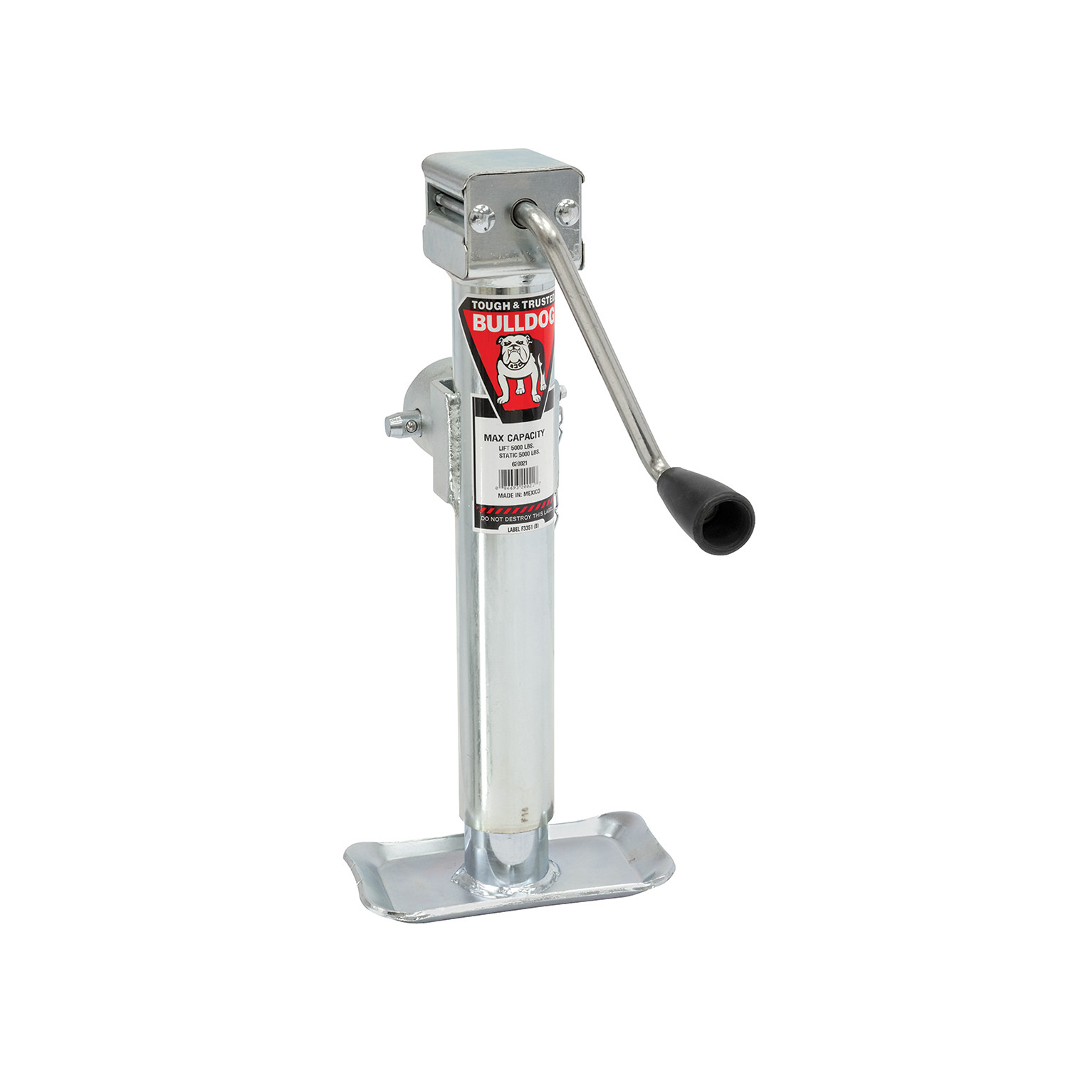
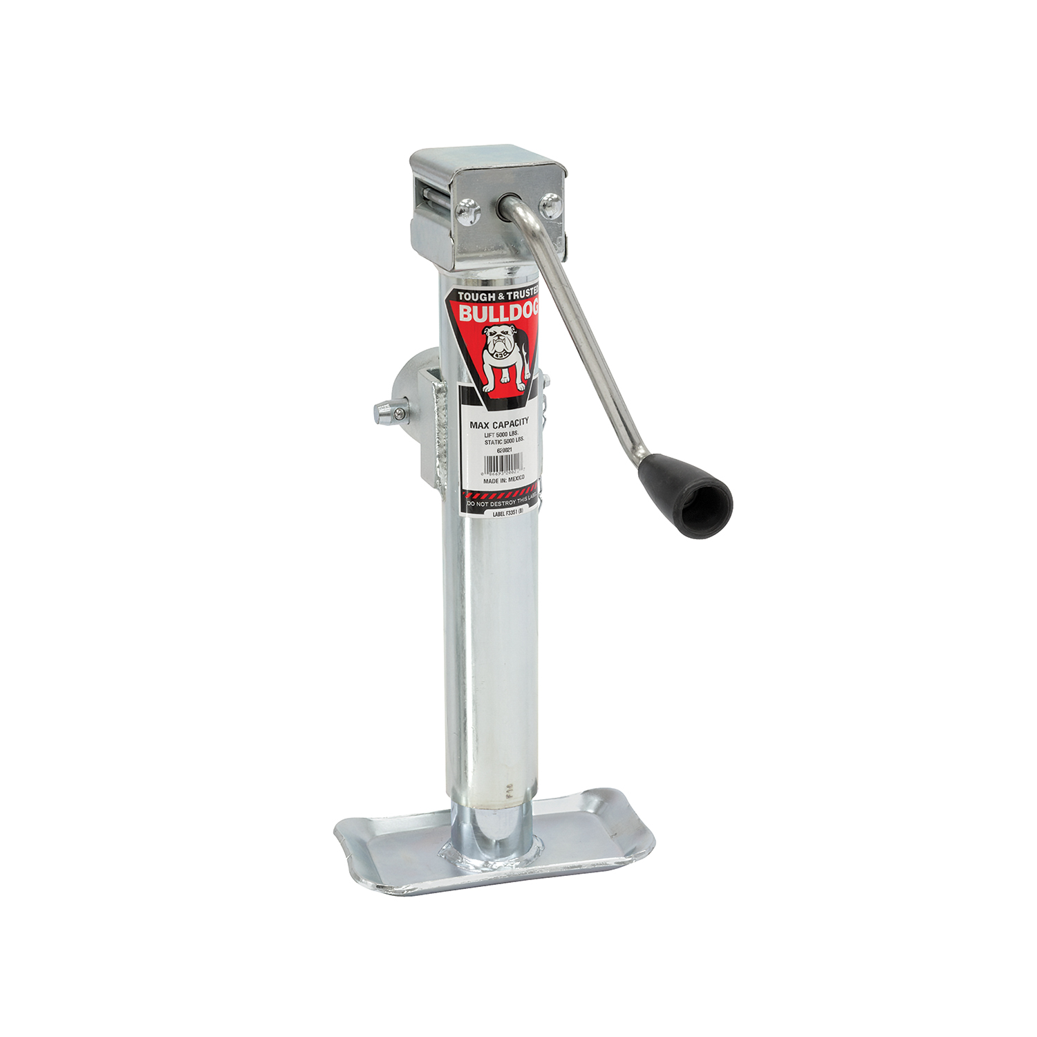
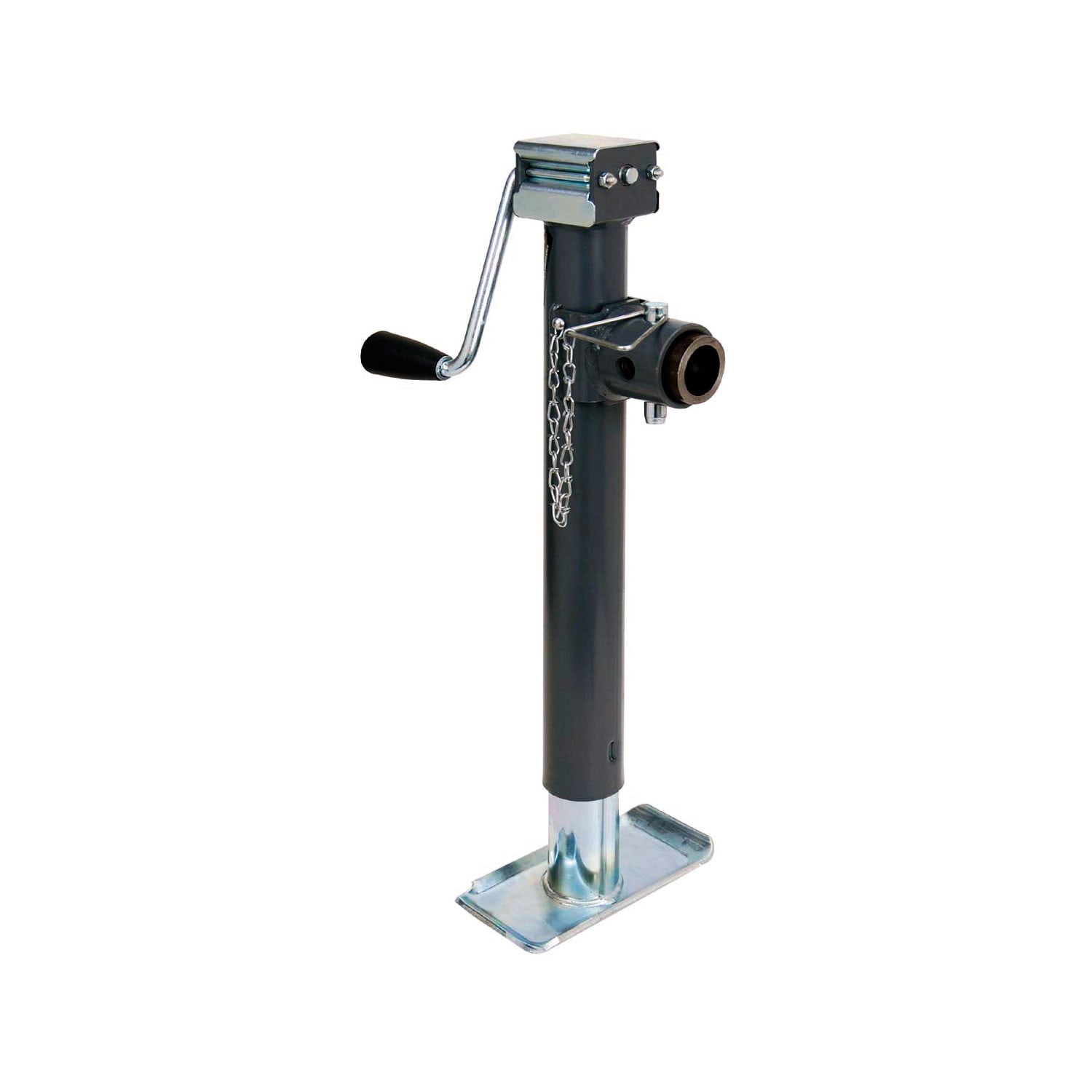
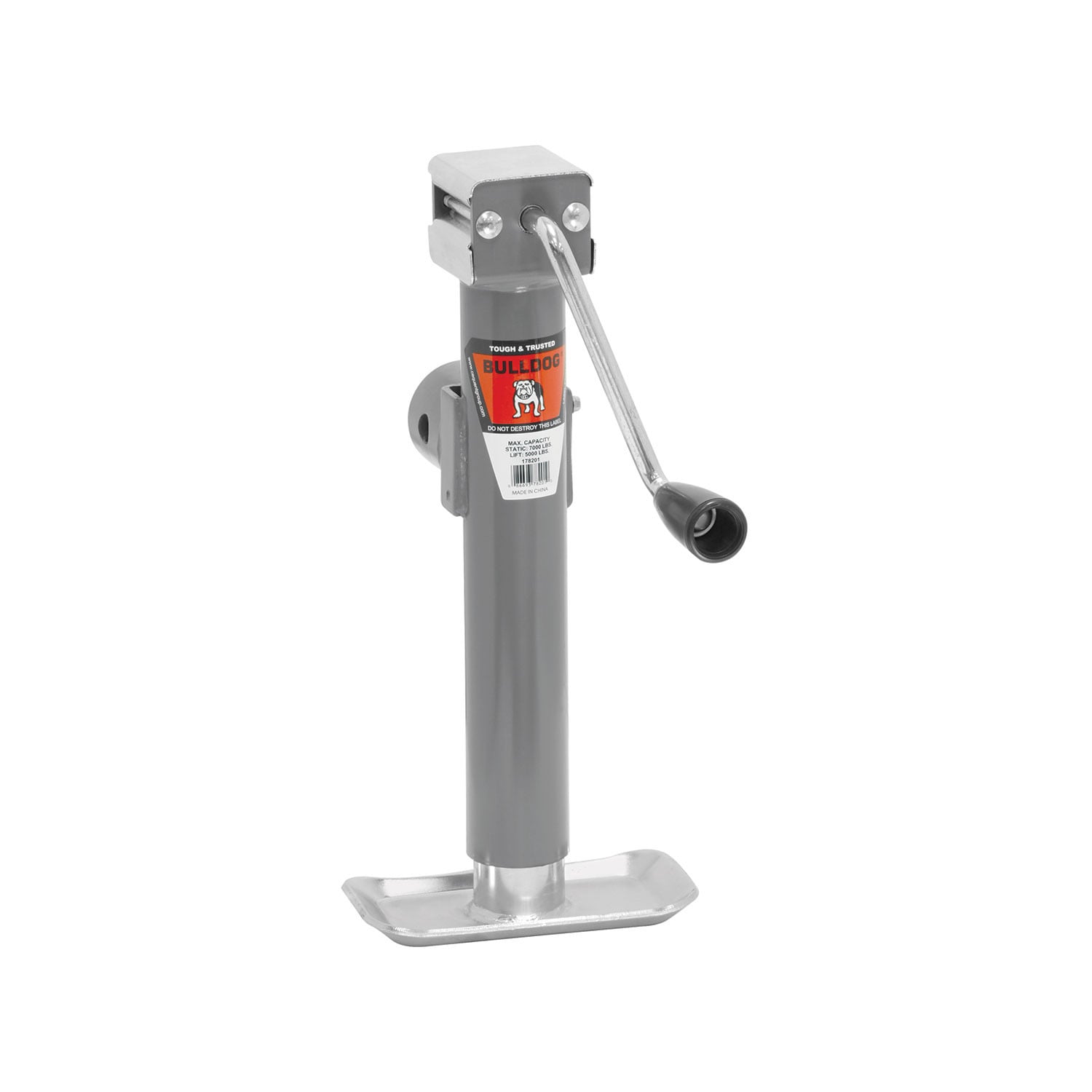
Bulldog Round Trailer Jack, No Mount, 5,000 lbs. Lift Capacity, Side Wind, Weld-On, 15 in. TravelBulldogOriginal price was $103.75. Current price is $95.73.Out of Stock
View productOur in-house experts typically reply within one business day.

Bulldog


Always the correct part
We know our products
Quality Products
Free Shipping!
Always the correct part
We know our products
Quality Products
Free Shipping!

BULLDOG round jacks are recognized as the industry standard by leading agricultrual, commercial, horse, livestock, and other trailer manufacturers. For more than three quarters of a centruy, BULLDOG jacks have been demonstrated to be the most reliable, field-proven jacks on the market.
| BRAND: | BULLDOG |
| PART NUMBER: | 620023 |
| WARRANTY: | LIMITED 5 YEAR WARRANTY |
| WEIGHT: | 16 LBS |
| CAPACITY: | 5,000 LBS. |
| FOOT PLATE SIZE: | 7.5 IN. X 3.9 IN. |
| COLOR: | SILVER |
| TRAVEL: | 15 IN. |
| MATERIAL: | STEEL |
| ATTACHED WHEELS: | NO |
| CLEARANCE: | 6.2 IN. |
| CYLINDER DIAMETER: | 2.25 IN. |
| EXTENDED: | 30.5 IN. |
| FINISH: | ZINC |
| FOOT LENGTH: | 7.5 IN. |
| HANDLE STYLE: | SIDEWIND |
| FOOT WIDTH: | 3.9 IN. |
| MODEL NUMBER: | 5 SM-15-0 W/P&C |
| PULL PIN DIAMETER: | 0.63 IN. |
| SPEEDY LIFT: | NO |
| RETRACTED: | 15.5 IN. |

Founded in 1920, Bulldog has become the standard for heavy-duty trailer connection hardware in agricultural, military and utility service. The line covers gooseneck hitches and couplers, A-frame and channel-mount trailer couplers with the Wedge-Latch mechanism, and heavy-duty jacks, built for unmatched strength, reliability and safety under demanding loads.
Bulldog was founded in 1920 and has spent more than a century supplying the connection hardware that heavy trailers depend on. Its market has always been the demanding end: agricultural, military and utility applications where a coupler failure is not an inconvenience but a serious incident. The brand summarises its position as Tough and Tested, and it sits within the Horizon Global towing group alongside Reese, Draw-Tite, Fulton, Tekonsha, Bargman and Wesbar.
Gooseneck equipment is the brand's signature. Gooseneck hitches mount in the truck bed over the rear axle, which places the load where the chassis can carry it properly and allows far tighter turning than a receiver hitch permits. Matching gooseneck couplers attach at the trailer end, in round tube and square configurations across the capacity range used by livestock, equipment and flatbed trailers.
The conventional trailer coupler range is built around the Wedge-Latch mechanism, which uses a wedge to take up wear between coupler and ball rather than relying on a fixed clamp that loosens over time. That matters on a trailer accumulating hard miles, where slack in the coupling shows up as noise and shock loading. Couplers are offered in A-frame form for standard tongues and in channel-mount form for straight tongue and fabricated frames, with adjustable channel versions that let a coupler be positioned to suit the tongue height.
Heavy-duty jacks complete the line, sized for the tongue weights that gooseneck and equipment trailers generate. Across the range the emphasis is consistent: forged and heavy-section components, load ratings backed by testing, and hardware specified for agricultural, military and heavy-duty commercial use rather than occasional recreational towing.
Experts available to answer your questions
Call 888-634-94945 Years
A tongue jack is a device mounted to a trailer tongue that raises and lowers the front of the trailer for coupling and uncoupling from the tow vehicle. It supports the tongue weight when the trailer is stationary. Cequent Performance Products manufactures tongue jacks in multiple styles including bolt-on rack jacks, snap ring models, bolt-thru models, A-plate jacks, and weld-on direct-mount versions, with optional drop feet, drop legs, or caster wheels for ground support.
Tongue jacks are available in five main mounting styles: (1) Bolt-on rack jacks, (2) Bolt-on mounting brackets, (3) Snap ring models, (4) Bolt-thru models with bushing, and (5) A-plate jacks designed for A-plate couplers. Additionally, direct-mount (weld-on) and weld-on pivot tube mounts (for round or square pivot tubes) are available. Each style has specific installation requirements.
No. The manual explicitly states: 'These jacks are not designed for mounting to round tongues.' Tongue jacks are designed for flat or rectangular trailer tongues. If you have a round tongue, consult the manufacturer at 1-800-521-0510 or www.cequentgroup.com for alternative solutions.
No. Bolt-on jacks must match the correct mounting hole pattern for your specific tongue size. The gap between the mounting bolts and the tongue must not exceed 1/16 inch. Before purchasing or installing, confirm that the jack's bolt pattern aligns with your trailer tongue width. If uncertain, contact Cequent Performance Products at 1-800-521-0510.
No. A-plate jacks are designed specifically for mounting to trailers with A-plate couplers only. If your trailer has a different coupler type, you will need a different jack mounting style such as bolt-on, snap ring, or direct-mount.
Bolt-on tongue jacks include supplied bolts and locknuts for mounting. The exact quantity and size depend on the specific jack model. Standard bolt-on installations use 4 bolts with locknuts. For A-plate jacks, three 3/8-16 grade 5 bolts with washers are required (may be supplied or purchased separately). Always verify the hardware included with your specific product.
For bolt-on installations, you will need a wrench or socket set to tighten the bolts and locknuts to the specified torque of 25 ft. lbs. For weld-on installations, an AWS certified welder is required. For snap ring or bolt-thru models, basic hand tools are needed. The manual does not specify additional specialized tools beyond these.
Yes. The manual states: 'All welding must be performed by an AWS certified welder.' This applies to direct-mount installations, A-plate installations, and weld-on pivot tube mounts. Do not attempt to weld the jack yourself unless you are AWS certified. Improper welding can result in product failure and safety hazards.
Before installation, confirm that there will be no interference from the tow vehicle, tongue, ground, or any other mounted accessories while stationary or in motion. Check for interference in all positions, including handle swing and swivel positions if applicable. After installation is complete, check for clearance again. Specifically verify clearance of the handle, trailer light cables, and coupler. This prevents damage during operation and towing.
Yes. The manual states: 'It is recommended to attach a bottom support plate to the bottom of the tongue' for A-plate jacks. The support plate should be welded to the bottom of the trailer frame using a 3/16 inch fillet weld. This provides additional structural support and must be performed by an AWS certified welder.
1) Place the gear housing on the tongue and insert the supplied bolts into holes corresponding to the tongue width. 2) Place the mounting bracket below the tongue with the flat surface against the tongue. 3) Secure with locknuts and torque to 25 ft. lbs. Ensure the gap between mounting bolts and tongue does not exceed 1/16 inch. After installation, check for clearance of the handle, trailer light cables, and coupler.
1) Place the jack against the tongue and position the mounting straps on the opposite side of the tongue. Align the holes in the mounting bracket with the holes in the mounting straps. 2) Insert the 4 bolts through the mounting bracket and mounting straps. The upper bolts should rest on the top of the tongue; the lower bolts should be less than 1/16 inch from the bottom of the tongue. 3) Secure with locknuts and torque to 25 ft. lbs. 4) Check for clearance of handle, trailer light cables, and coupler. The gap between mounting bolts and tongue must not exceed 1/16 inch.
1) Place the jack bracket over the mount and place the snap ring in the groove. 2) Seat the snap ring fully into the groove. Before installation, inspect the snap ring groove and remove any debris to ensure proper seating. The snap ring secures the jack bracket to the mount.
1) Place the jack bracket into the recessed opening on the mount. 2) Place the small end of the bushing into the jack bracket and onto the bolt. 3) Tighten the locknut until there is little movement in the bushing. Note: The bolt should be installed between the trailer tongue and mount; the jack bracket will be held by the bushing between the locknut and the mount.
1) All welding must be performed by an AWS certified welder. 2) If the A-plate is separate from the jack, align the jack (and foot, if equipped) with the jack and coupler as desired before welding. Use a 3/16 inch fillet weld. 3) Bolt the jack A-plate to the coupler using three 3/8-16 grade 5 bolts with washers, torque to 15-20 ft. lbs. 4) Weld the recommended support plate to the bottom of the trailer frame using a 3/16 inch fillet weld. 5) If your jack is a plain mount type, it may be mounted directly to a coupler with a 3/16 inch fillet weld. 6) Rack jacks with a similar A-plate incorporated into their design may be attached according to these instructions.
1) All welding must be performed by an AWS certified welder. 2) Place the jack at the desired location on the tongue. 3) Weld 1 inch in 2 locations on both sides of the jack using a 3/16 inch fillet weld. This creates four 1-inch welds total (two on each side). The same welding instructions apply to other weld-on mounts.
1) All welding must be performed by an AWS certified welder. 2) The non-beveled side of the pivot tube is welded to the tongue unless otherwise specified on hardware. 3) Place the weld-on pivot tube against the tongue and weld all around with a 3/16 inch fillet weld. Align one set of pivot mount holes vertically. 4) Mate the jack to the pivot tube and secure with the supplied pin. This applies to both round and square pivot tubes.
1) Insert the long spacer into the wheel. 2) Set the wheel into the caster body and place the bolt through the caster body and wheel. 3) Secure with the nut provided. For heavy duty casters, use 4 3/8 inch bolts, washers, and locknuts as shown in the manual. Note: Jack capacity is limited to the lesser of the jack or caster capacity.
For side-wind models: 1) Insert the long spacer into the roller followed by the thin spacer and the bolt. 2) Secure to the crank stem with the nut provided. For top-wind models: 1) Place the washer over the screw stem and then place the handle over the screw stem. 2) Secure the handle to the screw stem with the bolt and nut provided.
Torque all mounting bolts and locknuts to 25 ft. lbs. This applies to both bolt-on rack jacks and bolt-on mounting bracket installations. Do not exceed this torque value.
When bolting the jack A-plate to the coupler, use three 3/8-16 grade 5 bolts with washers and torque to 15-20 ft. lbs.
All weld-on installations require a 3/16 inch fillet weld. This applies to direct-mount installations, A-plate installations, and weld-on pivot tube mounts. All welding must be performed by an AWS certified welder.
The gap between the mounting bolts and the tongue must not exceed 1/16 inch (1.5 mm). This applies to bolt-on installations. Proper alignment ensures secure mounting and prevents movement during operation.
For direct-mount (weld-on) installation, weld 1 inch in 2 locations on both sides of the jack using a 3/16 inch fillet weld. This creates four 1-inch welds total. All welding must be performed by an AWS certified welder.
Before towing, fully retract and rotate the jack. If using an optional drop foot or caster, always remove it before towing to maximize ground clearance. Failure to do so may cause the jack to contact the ground or other obstacles during towing, resulting in damage or loss of control.
Never exceed the maximum rated capacity stamped on the product or shown on decals. The jack capacity is limited to the lesser of the jack, footplate, or caster wheel capacity. To determine the exact capacity of your jack, refer to the stamped markings or decals on the product. If uncertain, contact Cequent Performance Products at 1-800-521-0510 or www.cequentgroup.com.
No. Tongue jacks are designed for vertical loading only. Excessive side forces may cause jack failure and must be avoided. Always apply load vertically to the jack.
Before manually moving the trailer, crank the jack to its lowest position. This reduces the tongue height and makes manual movement easier and safer.
Never position any part of your body under any portion of the jack or the load being supported. Secure the load, vehicle, and trailer from rolling by blocking the wheels when operating the jack or coupling the trailer. Do not allow children to play on or around the jack or the load. Do not use the jack as a transport device for the implement it is attached to; minimize movement of the implement while the jack is under load.
When using a drop foot or drop leg, make certain the supplied pin is fully inserted through both sides of the inner tube and the drop tube before using the jack. If using an optional drop foot or caster, always remove it before towing to maximize ground clearance. Never attempt to adjust the drop foot or drop leg when there is any load on the jack.
If your jack has a pivot tube mount, make certain the pivot pin is fully inserted through both sides of the pivot tube and the pivot mount before using the jack. This ensures the jack is properly secured and will not shift during operation.
If your jack is a swivel jack, lock the plunger pin into a hole in the mounting bracket before raising or lowering the tongue. This prevents unwanted rotation of the jack during operation.
No. If your jack is a rack jack, do not raise the gear housing above the inner tube. Doing so may cause damage to the jack or loss of load support.
The following procedures should be performed at least annually: For side-wind models, lubricate the internal gearing and bushings. For top-wind models, apply lightweight oil to the screw stem. If the jack is used in a marine environment, flush the jack assembly and bushings with fresh water and apply fresh lubricant. Refer to the maintenance section for specific lubrication points and procedures.
For side-wind models, apply a small amount of automotive grease to the internal gearing by removing the jack cover, or if equipped, use a needle nose applicator or standard grease gun on the lubrication point found on the side of the jack near the crank. Rotate the jack handle to distribute the grease evenly. Apply a lightweight oil to the handle unit at both sides of the tube. If equipped, the axle bolt and nut assembly of the caster wheel must also be lubricated with the same lightweight oil. Perform this annually.
For top-wind models, apply a lightweight oil to the screw stem. Perform this annually. If the jack is used in a marine environment, flush the jack assembly and bushings with fresh water and apply fresh lubricant.
If the jack is used in a marine environment, flush the jack assembly and bushings with fresh water and apply fresh lubricant. This should be done at least annually to prevent corrosion and salt damage.
Always replace bent, broken, or worn parts before using the jack. Do not operate a jack with damaged components, as this may result in failure and safety hazards. Use only Cequent Performance Products parts or parts of equal quality for repair. Replacement parts are available through Cequent Performance Products Customer Service at 1-800-521-0510.
After installation is complete, check for interference again in all positions, including handle swing and swivel positions if applicable. Verify clearance of the handle, trailer light cables, and coupler. Ensure all bolts are torqued to specification and all welds are complete and sound. Test the jack operation to confirm it raises and lowers smoothly.
Tongue jacks are available in multiple mounting styles (bolt-on, snap ring, bolt-thru, A-plate, direct-mount, and pivot tube). Bolt-on models must match your tongue width with a gap not exceeding 1/16 inch. A-plate jacks fit only A-plate couplers. Jacks are not designed for round tongues. Verify your trailer's coupler type and tongue dimensions before purchasing.
Yes, if you choose a weld-on model (direct-mount, A-plate, or pivot tube). All welding must be performed by an AWS certified welder. Bolt-on, snap ring, and bolt-thru models do not require welding and can be installed with basic hand tools.
Bolt-on models: torque to 25 ft. lbs. A-plate models: torque to 15-20 ft. lbs. All weld-on models require a 3/16 inch fillet weld performed by an AWS certified welder.
Fully retract and rotate the jack before towing. If using an optional drop foot or caster, remove it before towing to maximize ground clearance. Never tow with the jack extended or with optional ground-contact accessories attached.
Never exceed the maximum rated capacity stamped on the product. Capacity is limited to the lesser of the jack, footplate, or caster wheel capacity. Refer to the decals on your specific jack or contact Cequent Performance Products at 1-800-521-0510 for the exact rating.
Perform lubrication at least annually. Side-wind models require automotive grease on internal gearing and lightweight oil on the handle. Top-wind models require lightweight oil on the screw stem. In marine environments, flush with fresh water and relubricate.
Confirm no interference from the tow vehicle, tongue, ground, or accessories in all positions including handle swing and swivel. Verify the correct mounting hole pattern for your tongue width. For A-plate jacks, confirm your trailer has an A-plate coupler. Check clearance again after installation.
Before installing the snap ring, inspect the snap ring groove and remove any debris. Seat the snap ring fully into the groove. If debris is present, clean the groove thoroughly before attempting installation again. Ensure the snap ring is fully seated to prevent the jack bracket from shifting.
Tighten the locknut until there is little movement in the bushing. The bolt should be installed between the trailer tongue and mount, with the jack bracket held by the bushing between the locknut and the mount. If movement persists after tightening, inspect the bushing for wear or damage and replace if necessary.
For side-wind models, the internal gearing and bushings may need lubrication. Apply a small amount of automotive grease to the internal gearing by removing the jack cover or using a needle nose applicator on the lubrication point near the crank. Rotate the jack handle to distribute the grease evenly. For top-wind models, apply lightweight oil to the screw stem. If the jack still does not operate smoothly, inspect for bent or broken parts and replace before using.
Ensure the pivot pin is fully inserted through both sides of the pivot tube and the pivot mount. If the pin continues to shift, inspect the pin and the holes for wear or damage. Replace the pin if it is bent or worn. Do not use the jack until the pivot pin is fully and securely seated.
When using a drop foot or drop leg, make certain the supplied pin is fully inserted through both sides of the inner tube and the drop tube before using the jack. If the pin will not fully insert, inspect the holes for debris or damage. Clean the holes and try again. Do not use the jack until the pin is fully seated.
Lock the plunger pin into a hole in the mounting bracket before raising or lowering the tongue. If the pin will not lock, inspect the holes in the mounting bracket for debris or damage. Clean the holes and try again. Do not raise or lower the jack until the plunger pin is locked in place.
Retorque all mounting bolts to specification: 25 ft. lbs. for bolt-on models, or 15-20 ft. lbs. for A-plate models. Check bolts periodically, especially after the first few uses, as vibration during towing may cause them to loosen. If bolts continue to loosen, inspect the bolt holes for damage or wear and replace damaged components.
Before installation, check for interference in all positions including handle swing and swivel positions if applicable. After installation, verify clearance of the handle, trailer light cables, and coupler. If interference is found, the jack may not be compatible with your trailer configuration or may be installed incorrectly. Consult the installation instructions for your specific mounting style or contact Cequent Performance Products at 1-800-521-0510.
| Part Number | Model Number | Description | Lift Capacity (lbs.) | Pin (in.) | Handle Style | Travel (in.) | A Retracted (in.) | B Extended (in.) | C Clearance (in.) |
|---|---|---|---|---|---|---|---|---|---|
| 158451 | TWS 158 DTSF w/P&C | Includes Footplate and Male Mating Mount | 2,000 | 9/16 | Topwind | 10.00 | 11.00 | 21.00 | 4.00 |
| 158452 | TWL 158 DTSF w/P&C | Includes Footplate and Male Mating Mount | 2,000 | 9/16 | Topwind | 15.00 | 14.50 | 29.50 | 10.00 |
| 158486 | TWL 158 DTSF w/P&C | Includes Footplate and Male Mating Mount | 2,000 | 9/16 | Topwind | 15.00 | 16.00 | 31.00 | 10.00 |
| 150441 | TWS 150 DTSF w/P&C | Includes Footplate, Clear Zinc Finish | 2,000 | 9/16 | Topwind | 10.00 | 11.00 | 21.00 | 4.00 |
| 158109 | SWS 158 DTSF w/P&C | Includes Footplate and Male Mating Mount | 2,000 | 9/16 | Sidewind | 15.00 | 14.50 | 29.50 | 12.20 |
| 158151 | SWL 158 DTSF w/P&C | Includes Footplate and Male Mating Mount | 2,000 | 9/16 | Sidewind | 10.00 | 11.00 | 21.00 | 8.00 |
| 178101 | TWS 178 DTSF w/P&C | Includes Footplate and Male Mating Mount | 5,000 | 9/16 | Topwind | 10.00 | 11.25 | 21.25 | 6.00 |
| 178109 | TWS 178 DTSF w/P&C | Includes Footplate and Male Mating Mount | 5,000 | 9/16 | Sidewind | 15.00 | 15.20 | 30.50 | 6.20 |
| 178110 | TWS 178 DTSF | Includes Footplate and Male Mating Mount | 5,000 | 9/16 | Topwind | 10.00 | 10.50 | 16.80 | 8.50 |
| 178112 | TWS 178 DTSF | Includes Footplate | 5,000 | 9/16 | Topwind | 10.00 | 10.50 | 16.80 | 8.50 |
| 178151 | TWL 178 DTSF w/P&C | Includes Footplate and Male Mating Mount | 5,000 | 9/16 | Topwind | 15.00 | 14.70 | 29.70 | 10.00 |
| 178201 | SWS 178 DTSF w/P&C | Includes Footplate and Male Mating Mount | 5,000 | 5/8 | Sidewind | 10.00 | 10.40 | 20.80 | 6.40 |
| 178203 | SWL 178 DTSF w/P&C | Includes Footplate and Male Mating Mount | 5,000 | 5/8 | Sidewind | 15.00 | 15.00 | 30.30 | 6.40 |
| 620023 | 5 SM-15-0 w/P&C | Includes Footplate and Male Mating Mount | 5,000 | 5/8 | Sidewind | 15.00 | 15.50 | 30.50 | 6.20 |
| 620057 | 7 SM -15-0 w/P&C | Includes Footplate and Male Mating Mount | 7,000 | 5/8 | Sidewind | 15.00 | 16.00 | 31.00 | 4.65 |
| 198100 | TWS 198 DTSM w/P&C | Includes Footplate and Female Mating Mount | 7,000 | 5/8 | Topwind | 10.00 | 10.80 | 20.80 | 4.50 |
| 198200 | TWL 198 DTSM w/P&C | Includes Footplate and Female Mating Mount | 7,000 | 5/8 | Topwind | 15.00 | 15.80 | 30.80 | 4.25 |
| 198150 | SWS 198 DTSM w/P&C | Includes Footplate and Female Mating Mount | 7,000 | 5/8 | Sidewind | 10.00 | 11.00 | 21.00 | 5.00 |
| 198250 | SWL 198 DTSM w/P&C | Includes Footplate and Female Mating Mount | 7,000 | 5/8 | Sidewind | 15.00 | 16.00 | 31.00 | 5.00 |
On Sale Today
Original price was $121.25. Current price is $101.48.You save $19.77 (16%)
Free Shipping
Ships free on all orders
 Authorized Dealer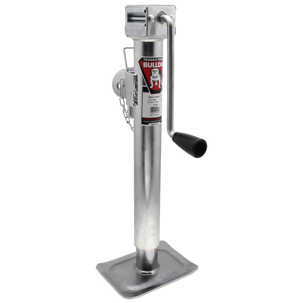

FREE ShippingFREE SHIPPING
Estimated delivery Sun, Sep 27 - Wed, Sep 30
Order before 2 PM EST Monday–Friday for same-day processing
Guaranteed safe & secure checkout
Jennifer
Ordered online. Shipment arrived on time and with all the correct parts. Great customer service and friendly staff. Also, pricing was great!
May 22, 2023