Ask a Question About This Product
Our in-house experts typically reply within one business day.
CURT
Verify Fitment
Select your vehicle to confirm this part fits.
2003 - 2005 Dodge Ram 2500
Confirmed to Fit
2003 - 2005 Dodge Ram 2500
Confirmed to Fit
2003 - 2010 Dodge Ram 3500
Confirmed to Fit
2006 - 2010 Dodge Ram 3500
Confirmed to Fit
2003 - 2010 Dodge Ram 3500
Confirmed to Fit
2011 - 2012 Ram 3500
Confirmed to Fit
2011 - 2012 Ram 3500
Confirmed to Fit
2011 - 2012 Ram 3500
Confirmed to Fit


Always the correct part
We know our products
Quality Products
Free Shipping!


Always the correct part
We know our products
Quality Products
Free Shipping!
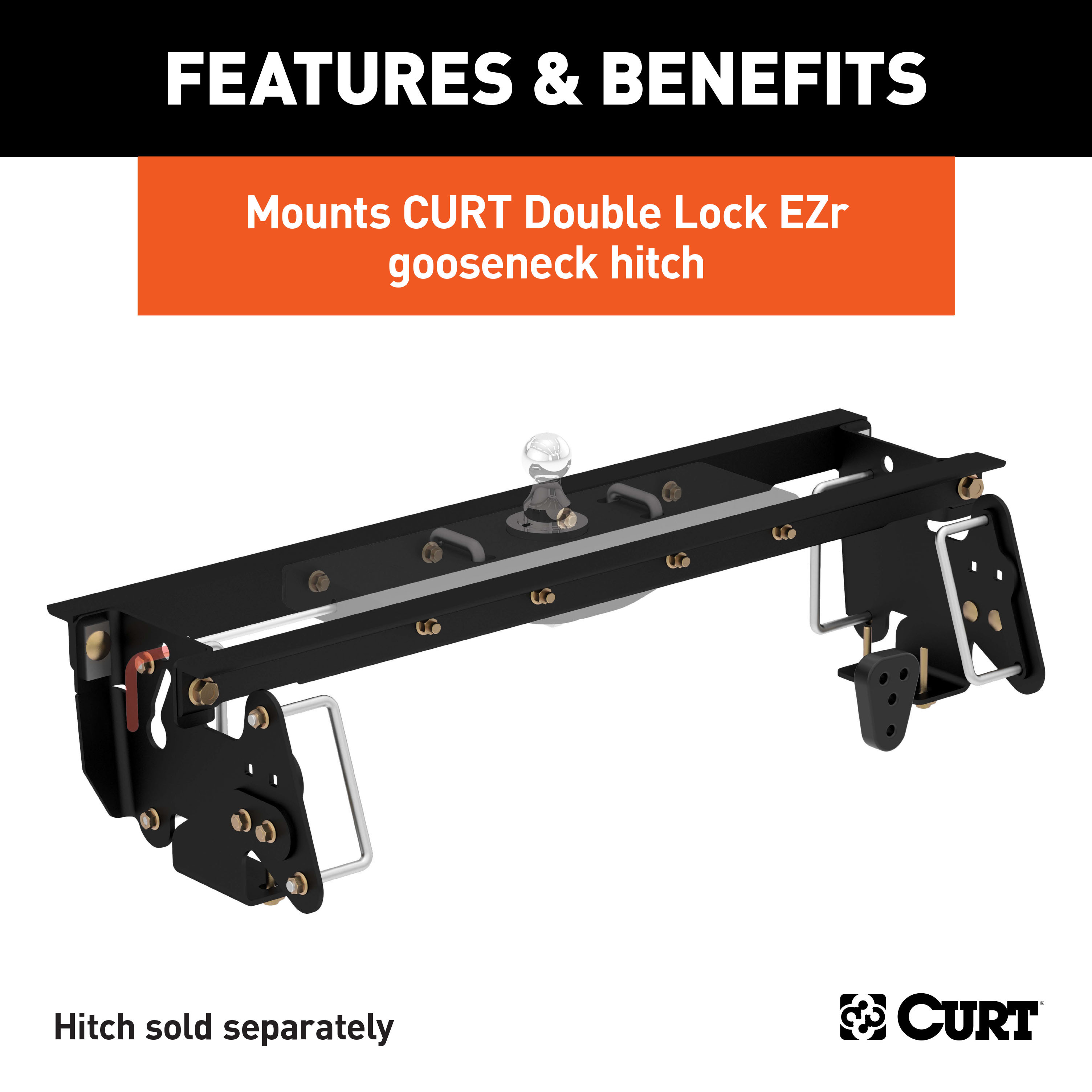
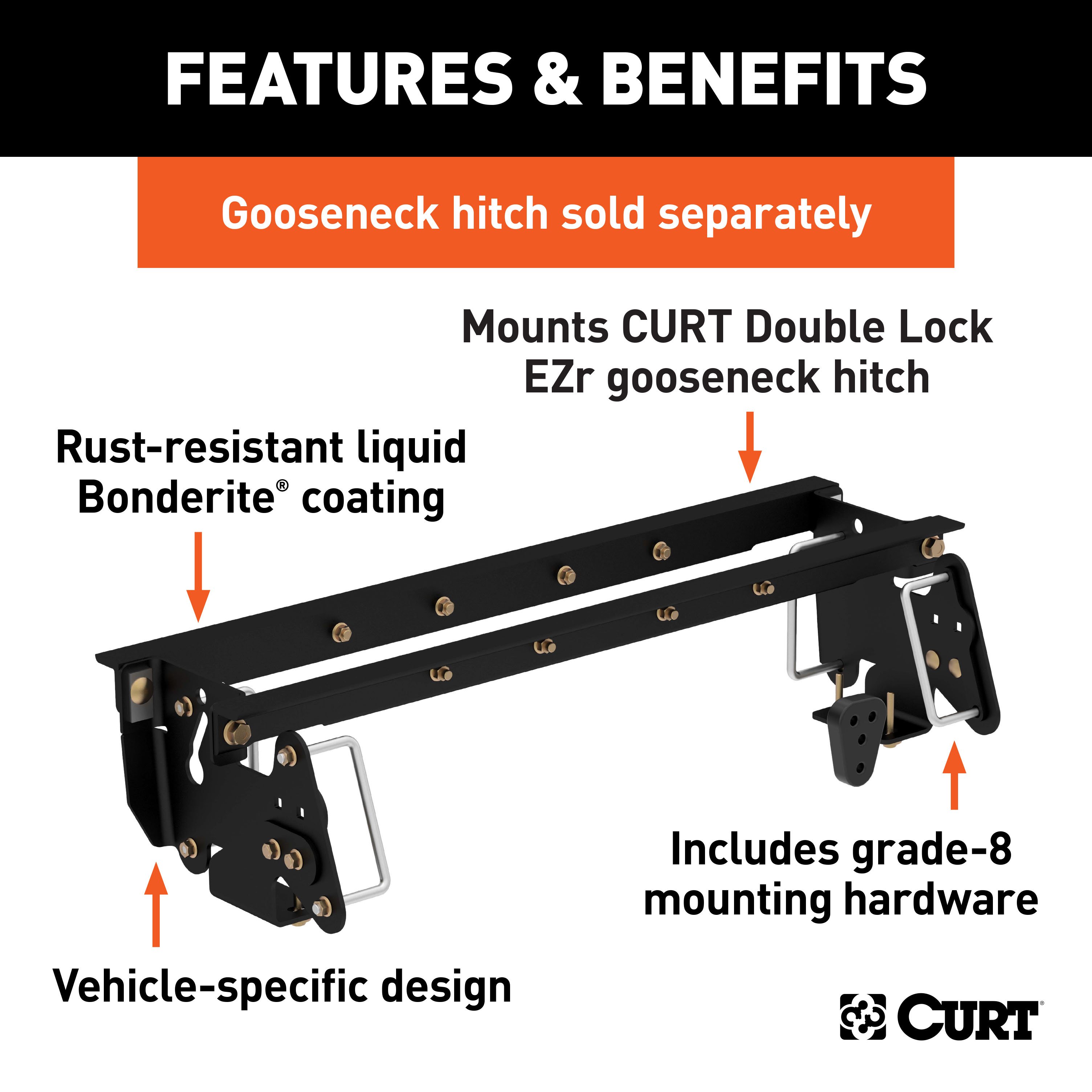
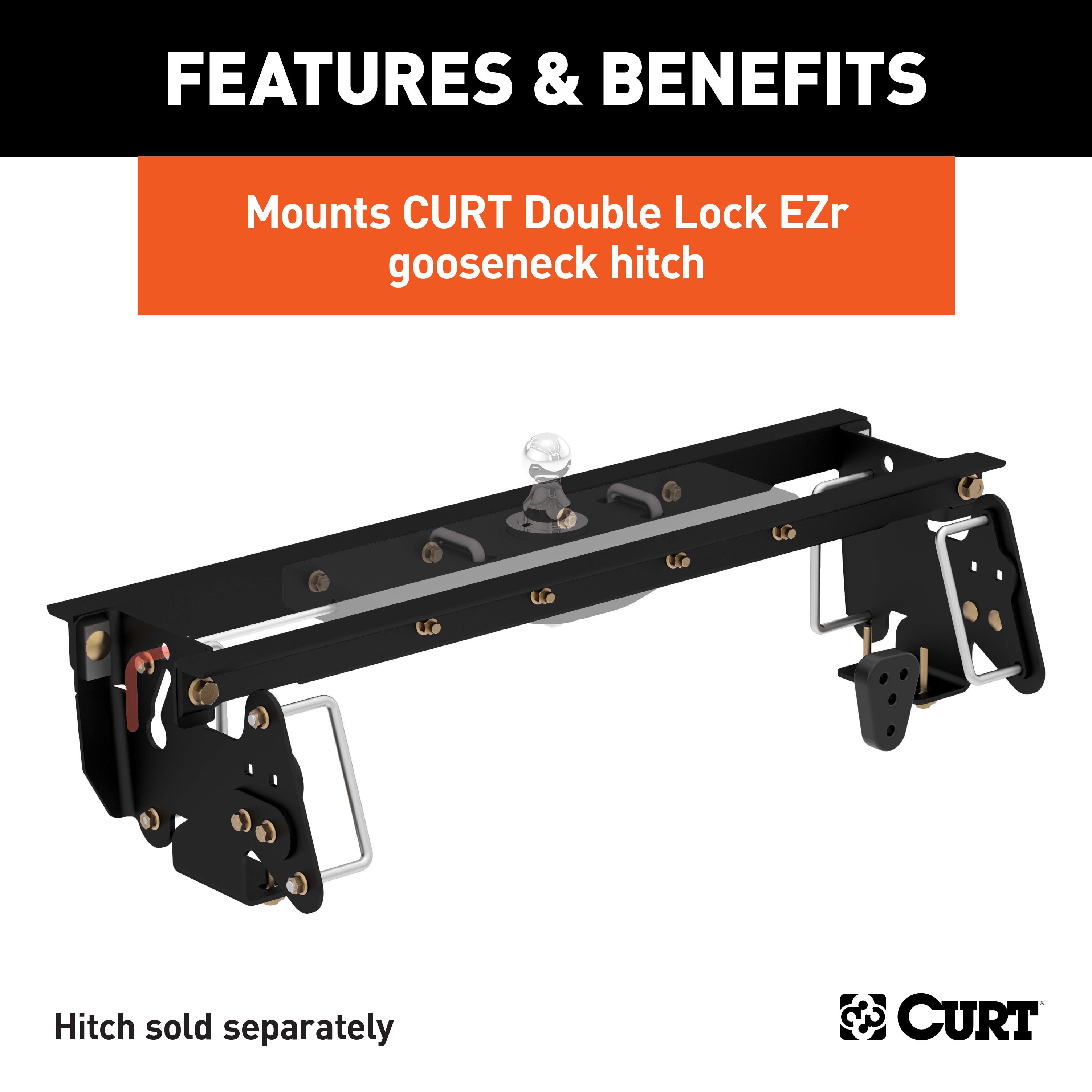
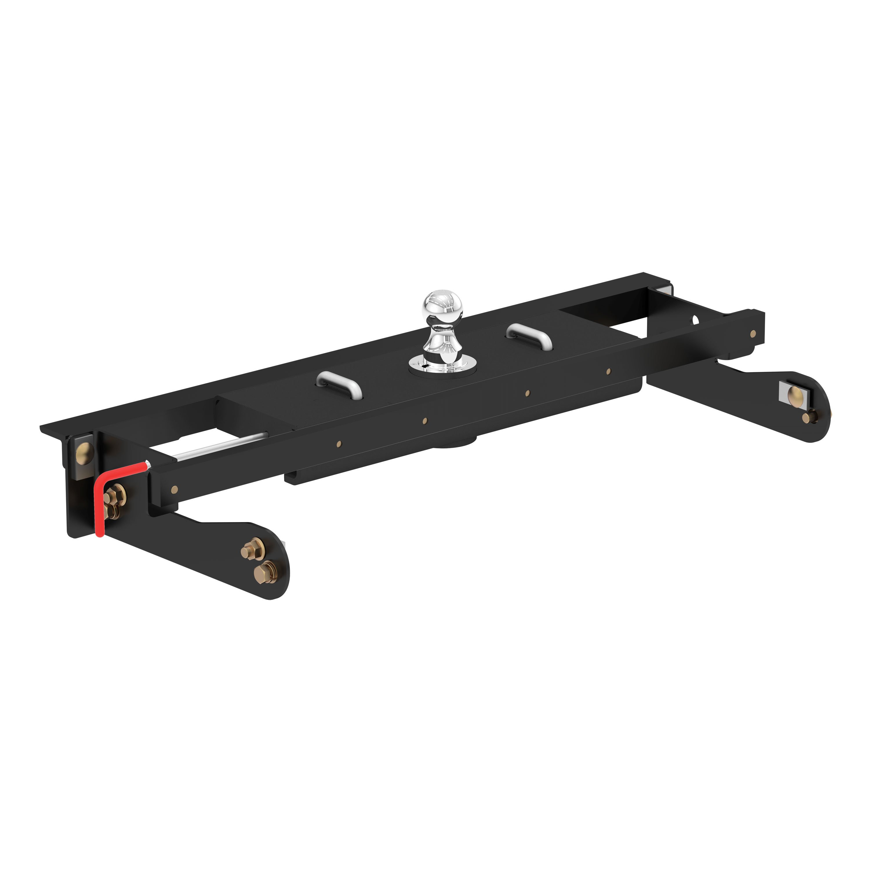
Includes mounting brackets only (gooseneck hitch sold separately)
Capacity limited to lowest-rated towing component
Includes mounting brackets only (gooseneck hitch sold separately)
Warranty: Limited Lifetime Warranty (One-Year Finish, One-Year Parts)
Finish: A-COAT
Installation Time Exact (Minutes): 0
Choosing the right gooseneck hitch is only half the battle in preparing your pickup truck for towing a gooseneck trailer. CURT gooseneck hitches are a premium option in the heavy-duty towing industry, but they are only one of the members in the heavyweight tag team that is CURT gooseneck towing. While a gooseneck hitch gets all the glory above the floor of your truck bed, gooseneck installation brackets provide sure footing and a solid foundation for that oversized gooseneck trailer. Gooseneck installation brackets work by bolting onto the frame of your truck, typically using pre-existing holes. With a set of brackets firmly bolted on, a gooseneck hitch is able to be attached and is given the strength it needs to manage the massive amount of weight of a gooseneck trailer. With so many gooseneck hitch options available from CURT, we wanted to make sure we offered the gooseneck installation products needed to give you a complete towing package. Our installation brackets fit multiple vehicles and hitch heads. This particular set of gooseneck installation brackets is specifically designed to mount a CURT Double Lock EZr gooseneck hitch on certain years of the Ram and Dodge Ram 2500 or 3500 (see application info to verify fitment). It features a laser-cut construction for a precise fit and is rated to the vehicle's maximum gross trailer weight capacity. With each gooseneck installation bracket sub kit, we provide the necessary hardware for an easier installation, and we coat our gooseneck brackets in a liquid A-coat to make sure rust and other potential damages are not a problem.

CURT offers a variety of high-quality trailer hitches and accessories for select vehicle models. Find the perfect fit for your towing needs at TowUniverse.
CURT, a Lippert brand, offers a complete line of towing products and is the leading manufacturer of custom-fit trailer hitches. We offer the broadest selection of custom-fit hitches, and each one is designed, welded, and coated in Wisconsin.
CURT is also a leader in flat towing products, as well as 5th wheel, gooseneck, and weight distribution hitches, ball mounts, electrical components, cargo solutions, and other towing accessories.
For everything from passenger cars and vans to full-size pickups and SUVs, CURT is 'The First Name in Towing Products®.'

Experts available to answer your questions
Call 888-634-9494Rediscover "Us" Time | Tested. Proven. Safe. Towing Products
10 compatible vehicles
| Year | Make & Model | Style | Notes |
|---|---|---|---|
| 2006 - 2010 | Dodge Ram 2500 | — | No Drilling Required Installation Time - |
| 2003 - 2005 | Dodge Ram 2500 | Crew Cab Pickup · 4-Door | No Drilling Required Installation Time - |
| 2003 - 2005 | Dodge Ram 2500 | Standard Cab Pickup · 2-Door | No Drilling Required Installation Time - |
| 2003 - 2010 | Dodge Ram 3500 | Crew Cab Pickup · 4-Door | No Drilling Required Installation Time - |
| 2006 - 2010 | Dodge Ram 3500 | Extended Crew Cab Pickup | No Drilling Required Installation Time - |
| 2003 - 2010 | Dodge Ram 3500 | Standard Cab Pickup · 2-Door | No Drilling Required Installation Time - |
| 2011 - 2013 | Ram 2500 | — | No Drilling Required Installation Time - |
| 2011 - 2012 | Ram 3500 | Crew Cab Pickup · 4-Door | No Drilling Required Installation Time - |
| 2011 - 2012 | Ram 3500 | Extended Crew Cab Pickup · 4-Door | No Drilling Required Installation Time - |
| 2011 - 2012 | Ram 3500 | Standard Cab Pickup · 2-Door | No Drilling Required Installation Time - |
The CURT Double Lock EZr Gooseneck Installation Brackets, Select Dodge, Ram 2500, 3500 Gooseneck Trailer Hitch Mount Kit (Part #BKDK60660) fits the following vehicles: 2003-2010 Dodge Ram 2500; 2003-2010 Dodge Ram 3500; 2011-2013 Ram 2500; 2011-2012 Ram 3500. Always verify your specific year, make, and model before ordering.
The CURT Double Lock EZr Gooseneck Installation Brackets, Select Dodge, Ram 2500, 3500 Gooseneck Trailer Hitch Mount Kit (Part #BKDK60660) fits 2003-2010 Dodge Ram 2500 models. The 2013 model year is the last year covered by this part number. For newer models, check for an updated version.
Yes, the CURT Double Lock EZr Gooseneck Installation Brackets, Select Dodge, Ram 2500, 3500 Gooseneck Trailer Hitch Mount Kit (Part #BKDK60660) is designed to fit the 2003-2010 Dodge Ram 2500.
The CURT Double Lock EZr Gooseneck Installation Brackets, Select Dodge, Ram 2500, 3500 Gooseneck Trailer Hitch Mount Kit (Part #BKDK60660) Drilling is not required for installation. Typical installation time is . Basic hand tools are typically all you need.
The 60660 is a gooseneck hitch subkit designed for Dodge 2500 and 3500 trucks with short or long beds. It includes two cross arms, driver and passenger side plates and brackets, spacer plates, an exhaust hanger, and all required fasteners (bolts, nuts, washers, spacers, and U-bolts). The subkit must be used with the 60612 center section (sold separately) to complete the gooseneck hitch installation.
Yes, the 60660 subkit is designed for both 2-wheel drive (4x2) and 4-wheel drive (4x4) Dodge 2500 and 3500 trucks. However, the installation differs: the side plate brackets attach to the top set of holes on the side plates for 2-wheel drive models and the bottom set of holes for 4-wheel drive models. Additionally, 2-wheel drive trucks require a clearance check when loaded and unloaded to verify the inverted ball will not interfere with the top of the differential.
Yes, the 60660 is designed for both short bed and long bed Dodge 2500 and 3500 trucks. However, on short bed models you must check for adequate turning clearance between the front of all trailers and the truck cab. The distance from cab to ball center is 43 9/16 inches on short bed trucks and 45 9/16 inches on long bed trucks.
The 60612 center section is required to complete the installation. The 60660 subkit is designed for use with the 60612 center section, which is not included in the subkit and must be purchased separately. Refer to the 60612 gooseneck hitch instructions for installation completion and operating procedures.
The spare tire must be lowered during installation. The manual does not specify permanent removal, but the tire must be temporarily removed to allow the cross arms to be inserted between the frame and the bottom of the truck bed.
On some models, the rearmost rubber exhaust isolator may need to be replaced with the included isolator (part CM-C655-EH) for additional clearance between the exhaust and the hitch. This is only needed on models with specific exhaust styles shown in the manual's Figure C. Some models may also require modification or removal of heat shields. Check your vehicle against the diagrams provided.
Brake, fuel, and electrical lines may need to be loosened or repositioned to provide clearance for the hitch hardware. The U-bolts must be positioned under all brake lines and wires. On 2012 and earlier Dodge models, the ground wire on the outside of the driver side frame rail must not be pinched between the driver side plate and frame—it may need to be loosened, rotated slightly, and retightened. Wire harness clips may also need to be unfastened from the inside of the driver side frame rail on some models.
Required tools are: safety glasses, ratchet, sockets in 15mm, 17mm, 3/4", and 15/16" sizes, crescent wrench, and torque wrench. The crescent wrench is used to bend the metal flange below the bed outward to allow the cross arms to be slid into position.
The subkit includes: four 1/2"-13 UNC 1" carriage bolts (10-10300), eight 1/2"-13 UNC 1-1/2" carriage bolts (10-10287), four .250" x 1.00" x 2.00" square hole spacers (CM-SP12), four 1/2"-13 x 4 x 7.25 x 1 3/4" square U-bolts (CM-1209-UBS), twenty 1/2"-13 UNC grade 8 serrated flange nuts (20-00062), four M10x1.5 40mm hex cap screws class 8.8 (10-10189), four 7/16" S-CON washers (30-00163), four .375" x 1.25" x 2.50" square hole spacers (CM-SP9), four 5/8"-11 UNC grade 8 serrated flange nuts (20-00105), four M10x1.5 70mm hex cap screws class 10.9 (10-10528), two 1/2"-13 UNC push nuts (20-00191), and four 5/8"-11 UNC 1-3/4" carriage bolts (10-10292).
The subkit includes two 2.50" x 2.00" x .375" cross arms (60660-CA), one exhaust hanger (CM-C655-EH), one .250" driver side plate (60660-DSWA), one .250" driver side bracket (60660-DSB), one .250" passenger side plate (60660-PSWA), one .250" passenger side bracket (60660-PSB), and two .313" spacer plates (60660-SP).
Plastic wheel well covers may need to be temporarily removed if your vehicle is equipped with them and if they are a style which prevents hitch installation. This is determined on a per-vehicle basis during the installation process.
Yes. You must remove the rubber bump stop from underneath each frame rail by removing two M10 bolts from each. Save the rubber bump stops for reinstallation, but the hardware removed will not be reinstalled.
Slide each cross arm between the frame and the bottom of the truck bed. The leg without holes must be against the bottom of the bed, and the leg with holes must face the rear of the vehicle for the forward cross arm (or face the front for the rearmost cross arm). Use a crescent wrench to bend the metal flange below the bed outward to allow the cross arms to slide into position. The cross arm can be used as a lever to add additional bend if needed. Insert each cross arm until it spans the frame rails, then slide it forward so it is next to the forward bed support.
Both cross arms are inserted between the frame and the bottom of the truck bed with the leg without holes against the bottom of the bed. The forward cross arm has its leg with holes facing the rear of the vehicle. The rearmost cross arm has its leg with holes facing the front of the vehicle. Both cross arms must span the frame rails and be positioned next to the forward bed support.
U-bolts must be positioned under all brake lines and wires. The forward U-bolt is placed on the inside of the driver side frame rail. The rearmost U-bolt is inserted over the inside of the driver side frame rail. Both U-bolts are then attached to the side plates with 1/2" hex flange nuts. One or two wire harness clips may need to be unfastened from the inside of the driver side frame rail on some models to position the U-bolts.
1. Raise the center section into position and loosely attach it to the front cross arm using four 1/2" x 1 1/2" carriage bolts with four CM-SP12 spacers and four 1/2" hex flange nuts. 2. Loosely attach the rearmost cross arm to the center section using four 1/2" x 1 1/2" carriage bolts and four 1/2" hex flange nuts. 3. Loosely assemble the side plates with brackets using 1/2" x 1" carriage bolts and 1/2" hex flange nuts. 4. Attach the driver side plate assembly over the forward U-bolt, then the rearmost U-bolt. 5. Attach the driver side plate assembly to the cross arms using 5/8" x 1 3/4" carriage bolts with CM-SP9 spacers and 5/8" hex flange nuts. 6. Repeat on the passenger side. All fasteners remain loose until the final torque sequence.
Two push nut bolt retainers (part 20-00191) are included as optional "helping hand" tools. If desired, insert two 1/2" x 1 1/2" carriage bolts through the centermost slots on the side of the center section that will fasten to the rear cross arm. Ensure the serrations in the bolt retainers are angled away from the center section, then push a bolt retainer onto the two carriage bolts. Use one of the included spacers as a tool to push the bolt retainers into position.
The gooseneck handle will come out on the side of the vehicle that the handle guide is located. This is determined by the 60612 center section design, not the 60660 subkit.
The center locator is a component that must be inserted into the center section cylinder prior to installing the center section. Ensure it is in place before raising the center section into position.
Verify the center section is centered on the vehicle by checking that the sides of the center section are in the same location on the bed ribs.
No. The manual explicitly states "NO DRILLING INTO FRAME" and "NO MEASURING DRILL LOCATIONS." The 60660 uses existing frame features and does not require drilling.
The 60660 does not require permanent modifications to the frame. However, some models may require modification or removal of heat shields, and the metal flange below the bed may need to be bent outward temporarily to allow the cross arms to be inserted. The rearmost rubber exhaust isolator may need to be replaced on some models for additional exhaust clearance. Brake, fuel, and electrical lines may need to be repositioned but not permanently altered.
Torque all fasteners in this order: First, torque the center section to the cross arms. Second, torque the side plate brackets to the truck frame. Third, torque side plate assemblies and the U-bolts to the side plates (tighten U-bolts slowly, alternating between top and bottom until equally tightened to a maximum of 40 ft-lbs). Fourth, torque the side plates to the cross arms. Final torque values: all 5/8" fasteners to 210 ft-lbs, all 1/2" fasteners to 110 ft-lbs, and all M10 hardware to 45 ft-lbs.
U-bolts must be tightened slowly, alternating between the top and bottom of the U-bolt until equally tightened to a maximum of 40 ft-lbs.
All 5/8" fasteners on the 60660 hitch must be torqued to 210 ft-lbs.
All 1/2" fasteners on the 60660 hitch must be torqued to 110 ft-lbs.
All M10 hardware on the 60660 hitch must be torqued to 45 ft-lbs.
The distance from cab to ball center on a short bed truck is 43 9/16 inches (measured between 72 and 82 inches of truck bed length).
The distance from cab to ball center on a long bed truck is 45 9/16 inches (measured between 96 and 98 inches of truck bed length).
The 60660 subkit weighs 90 lbs.
On short bed models, check for adequate turning clearance between the front of all trailers and the truck cab. On 2-wheel drive trucks, a clearance check must be performed when the truck is both loaded and unloaded to verify the inverted ball will not interfere with the top of the differential. Use the clearance calculation formula provided in the manual: (cab to ball center) minus (coupler overhang, if present) minus (1/2 trailer width) equals minimum clearance. If the result is positive, the trailer will not interfere with the cab. If negative, the trailer will interfere.
Use this formula: (cab to ball center) minus (1/2 trailer width) equals minimum clearance. If your trailer has a coupler overhang, use: [(cab to ball center) minus (coupler overhang)] minus (1/2 trailer width) equals minimum clearance. If the result is positive, the trailer will not interfere with the cab. If the result is negative, the trailer will interfere with the cab. For reference, 8-foot-wide trailers typically taper to 6 feet at the coupler, and 7-foot-wide trailers taper to 5 feet at the coupler.
The maximum torque for U-bolts is 40 ft-lbs. Tighten them slowly, alternating between the top and bottom of the U-bolt until equally tightened.
On 2012 and earlier Dodge models, a ground wire is located on the outside of the driver side frame rail. This ground wire must not be pinched between the driver side plate and the frame. The wire may need to be loosened, rotated slightly, and retightened to allow the plate to be put into position.
The manual does not specify that the battery must be disconnected for 60660 subkit installation. However, since brake and electrical lines may need to be repositioned, consult your vehicle's service manual or a professional installer if you are uncomfortable working near electrical components.
After installation, verify the center section is centered on the vehicle by checking that the sides of the center section are in the same location on the bed ribs. Then follow the complete torque sequence specified in the manual. After installation is complete, refer to the 60612 gooseneck hitch instructions for final installation steps and operating procedures.
Periodically check the gooseneck hitch to ensure that all fasteners are tight and that all structural components are sound. The manual does not specify an exact interval, but regular inspection is recommended before each use or towing operation.
The manual does not specify a retorque interval. However, it does state that you should periodically check the hitch to ensure all fasteners are tight and all structural components are sound. It is recommended to check fastener tightness before each towing operation.
Yes, the 60660 subkit fits Dodge 2500 and 3500 trucks with short or long beds, in both 2-wheel drive and 4-wheel drive configurations. It must be used with the 60612 center section (sold separately). On short bed models and 2-wheel drive trucks, clearance checks are required.
You need a ratchet, sockets (15mm, 17mm, 3/4", 15/16"), crescent wrench, torque wrench, and safety glasses. A torque wrench is essential for proper fastener tightening.
No drilling into the frame is required. The 60660 uses existing frame features. Some models may require heat shield modification or removal, and the metal flange below the bed may need to be bent outward temporarily to insert the cross arms.
Torque 5/8" fasteners to 210 ft-lbs, 1/2" fasteners to 110 ft-lbs, M10 hardware to 45 ft-lbs, and U-bolts to a maximum of 40 ft-lbs. Follow the specified torque sequence: center section to cross arms first, then side plate brackets to frame, then side plates and U-bolts, then side plates to cross arms.
On short bed models, verify adequate turning clearance between trailers and the truck cab. On 2-wheel drive trucks, check clearance when loaded and unloaded to ensure the ball does not interfere with the differential. Use the provided formula: (cab to ball center) minus (1/2 trailer width) must be positive.
These lines may need to be repositioned for clearance. U-bolts must be positioned under all brake lines and wires. On 2012 and earlier models, the ground wire on the driver side frame rail must not be pinched. Have these components checked and repositioned as needed during installation.
Lower the spare tire and temporarily remove plastic wheel well covers if they prevent hitch installation. Remove the rubber bump stops from underneath each frame rail (save them for reinstallation). Some models may require heat shield modification or removal.
Use a crescent wrench to bend the metal flange below the bed outward to allow the cross arm to slide into position. The cross arm itself can be used as a lever to add additional bend to the flange if needed. Ensure you are inserting the cross arm with the leg without holes against the bottom of the bed and the leg with holes facing the correct direction (rear for forward cross arm, front for rearmost cross arm).
One or two wire harness clips may be fastened to the inside of the driver side frame rail and preventing the U-bolt from being positioned. Unfasten these clips to allow the U-bolt to be placed into position. The U-bolt must be positioned under all brake lines and wires.
On 2012 and earlier Dodge models, the ground wire on the outside of the driver side frame rail may be pinched between the driver side plate and the frame. Loosen the ground wire, rotate it slightly, and retighten it to allow the plate to be put into position.
Verify the center section is centered on the vehicle by checking that the sides of the center section are in the same location on the bed ribs. If not centered, loosen the fasteners connecting the center section to the cross arms and adjust the position before retightening.
Perform the clearance calculation: (cab to ball center) minus (1/2 trailer width) equals minimum clearance. If your trailer has a coupler overhang, subtract that first: [(cab to ball center) minus (coupler overhang)] minus (1/2 trailer width). If the result is negative, the trailer will interfere with the cab. You may need to use a different trailer or check that the hitch is installed at the correct distance from the cab. For short bed trucks, the cab to ball center distance is 43 9/16 inches; for long bed trucks, it is 45 9/16 inches.
The manual requires that on 2-wheel drive trucks, a clearance check must be performed when the truck is both loaded and unloaded to verify the inverted ball will not interfere with the top of the differential. If interference is occurring, the hitch installation may not be suitable for your specific truck configuration. Consult the manufacturer or a professional installer.
On some models, the rearmost rubber exhaust isolator may need to be replaced with the included isolator (part CM-C655-EH) for additional clearance between the exhaust and the hitch. This is only needed on models with specific exhaust styles shown in the manual's Figure C. If your model requires this replacement, follow the instructions provided. If the exhaust still interferes, some models may require modification or removal of heat shields.
On Sale Today
Original price was $444.95. Current price is $275.99.


Quick Ship
In stock and ready to ship — order now!
Shipping from Lancaster, TXFREE SHIPPING
Estimated delivery Mon, Aug 31 - Wed, Sep 2
Order before 2 PM EST Monday–Friday for same-day processing
Guaranteed safe & secure checkout
No reviews have been added for this product.