
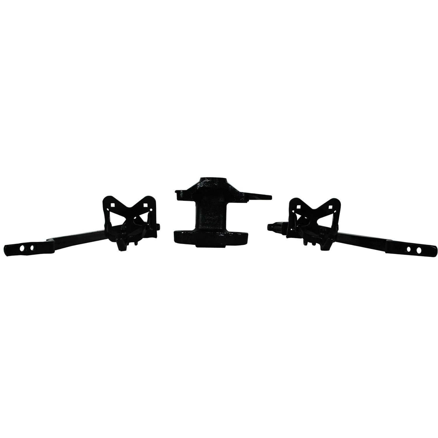
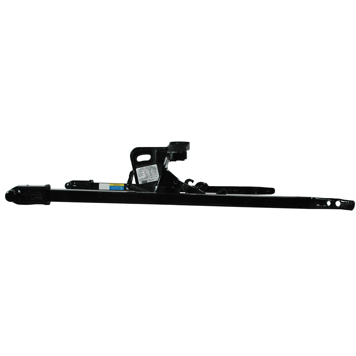
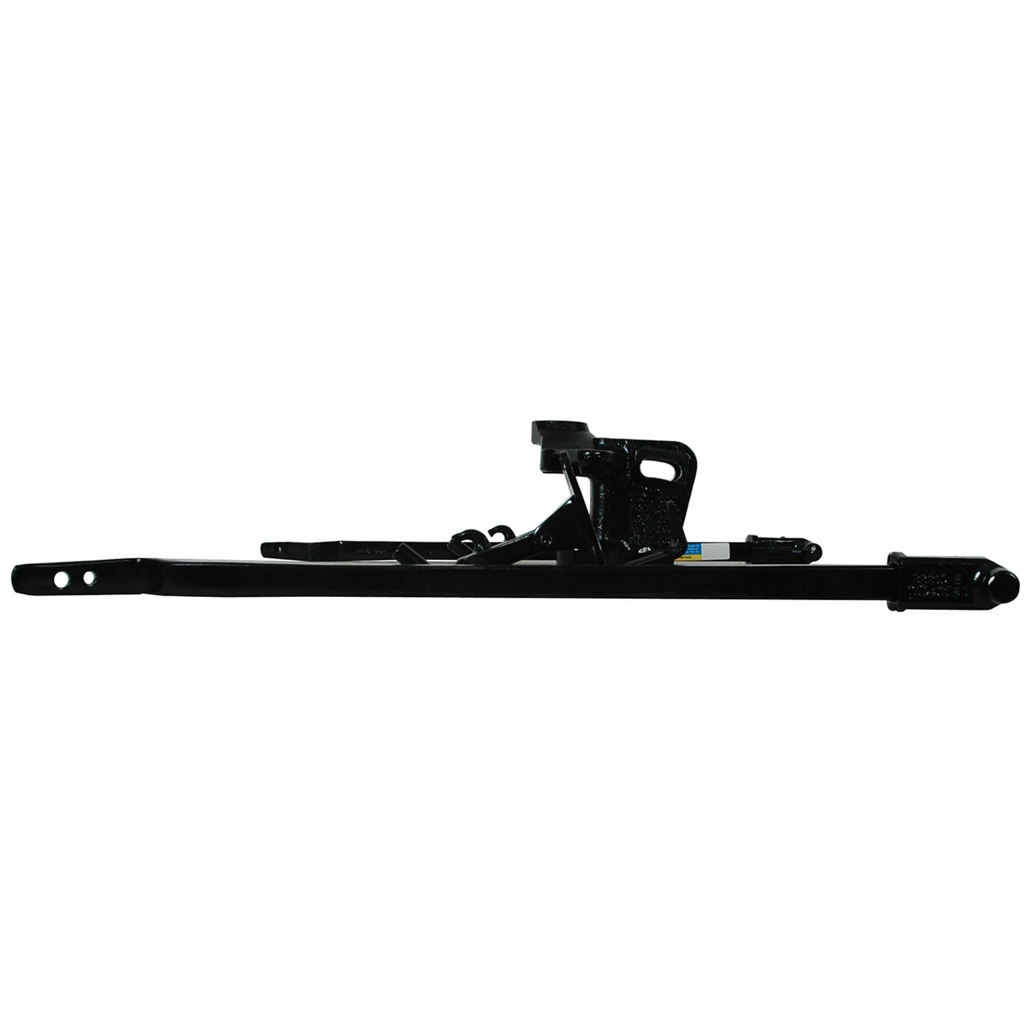
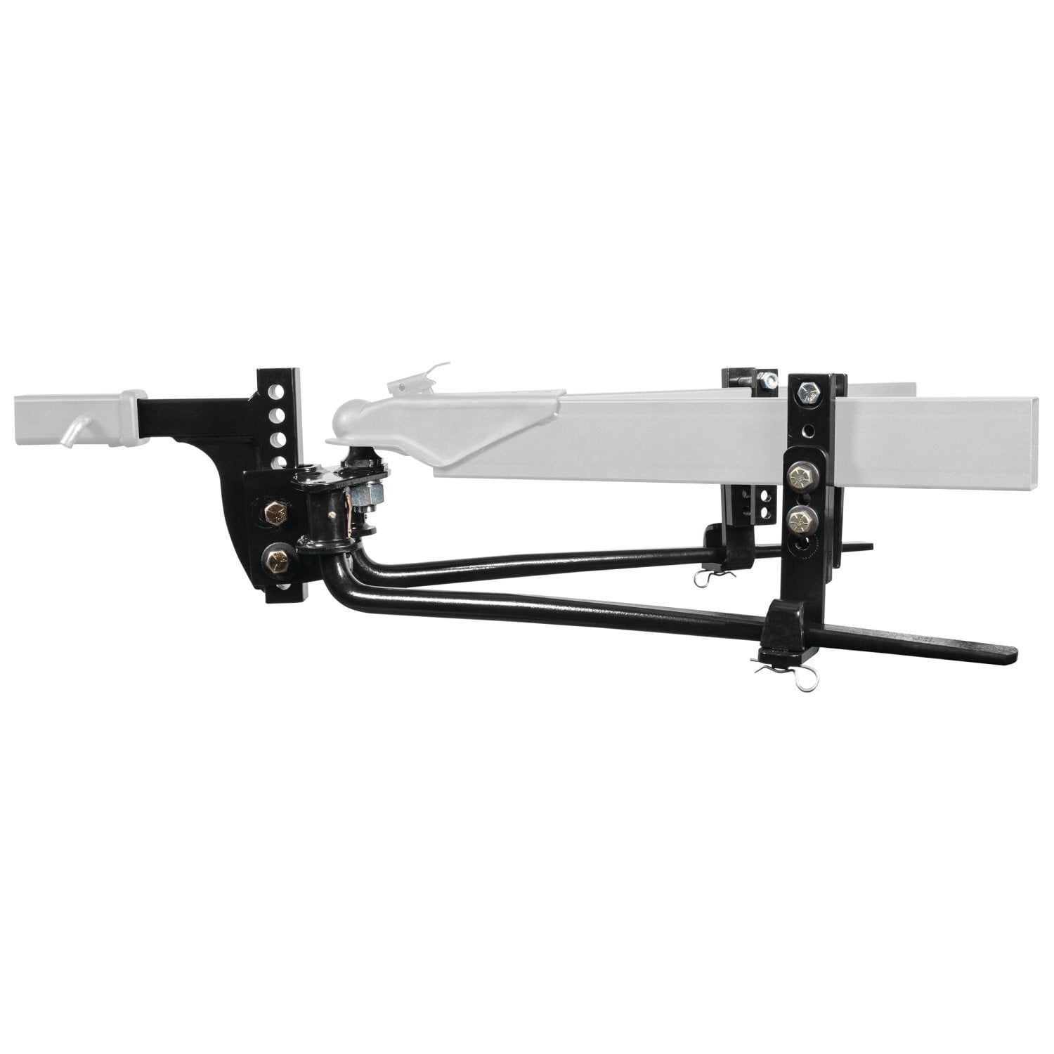
Reese Weight Distribution Kit, 8,000 lbs. Capacity, Shank IncludedReese$1,085.26Out of Stock
View productOur in-house experts typically reply within one business day.

Reese



Always the correct part
We know our products
Quality Products
Free Shipping!
Always the correct part
We know our products
Quality Products
Free Shipping!

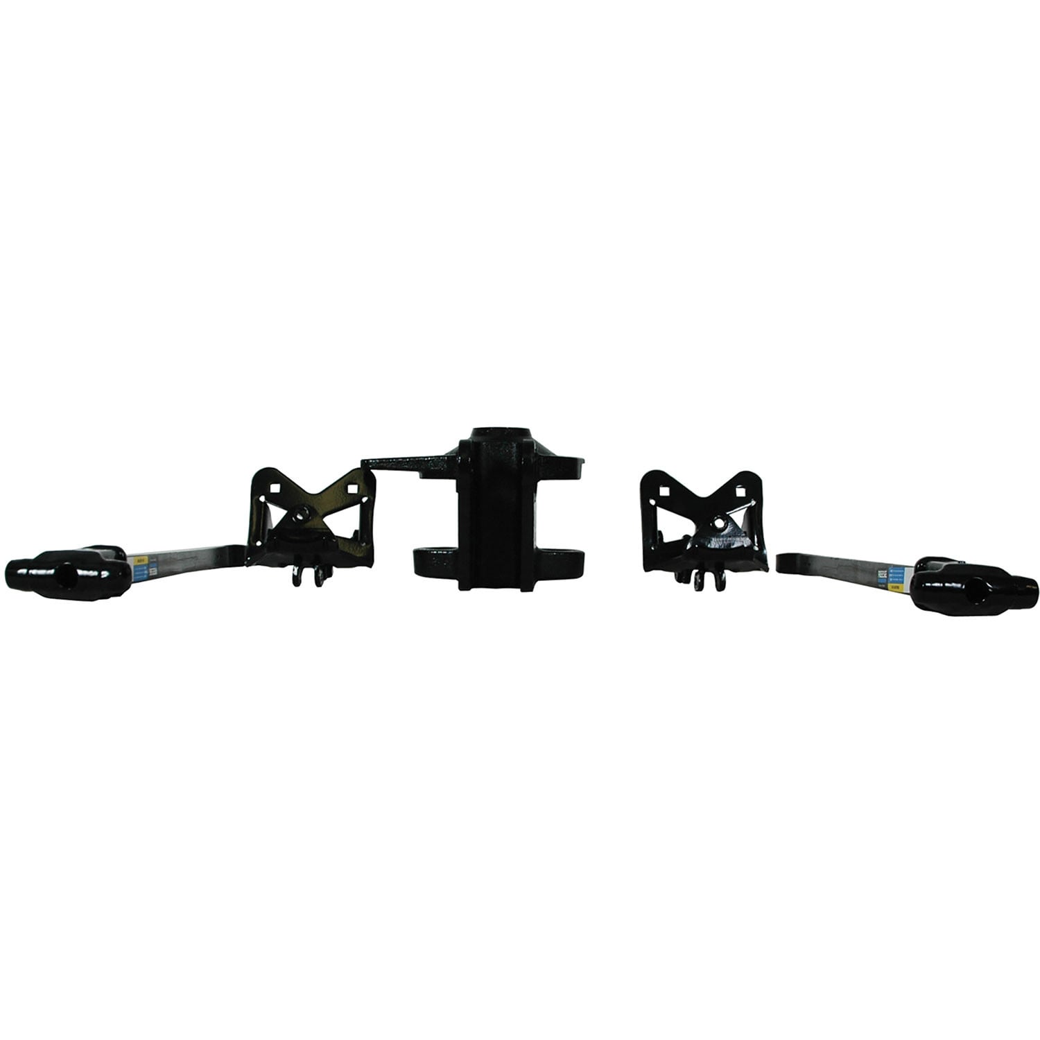
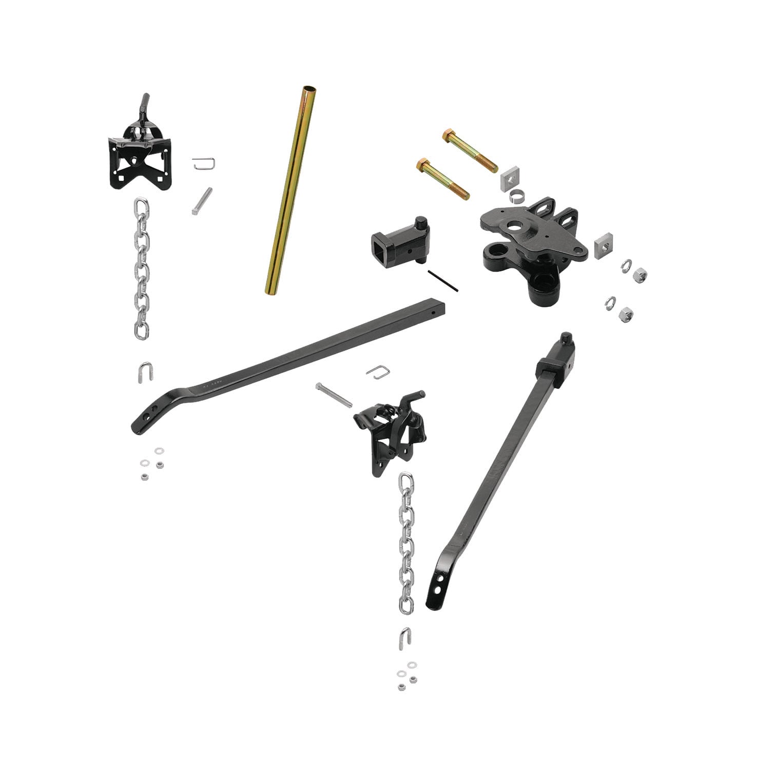
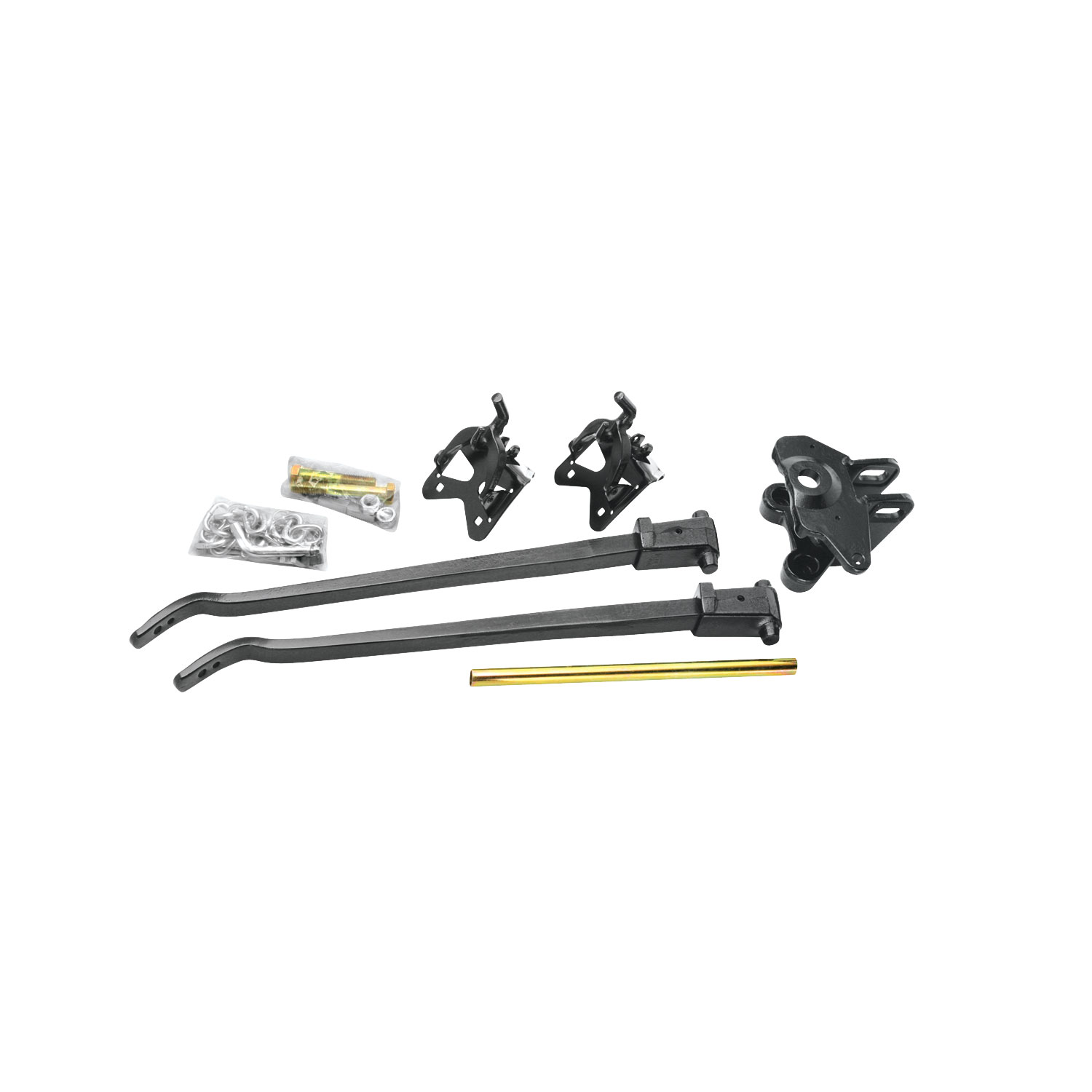
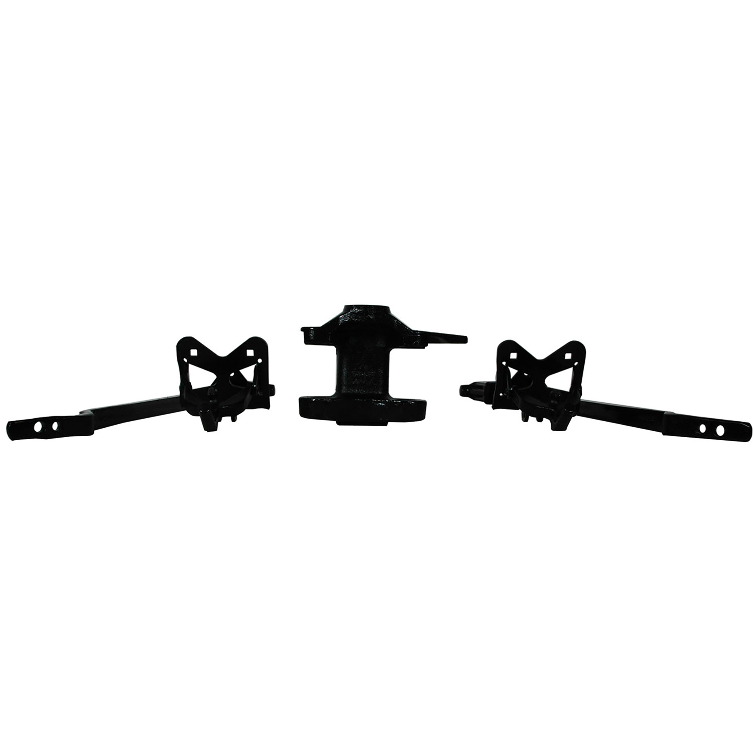
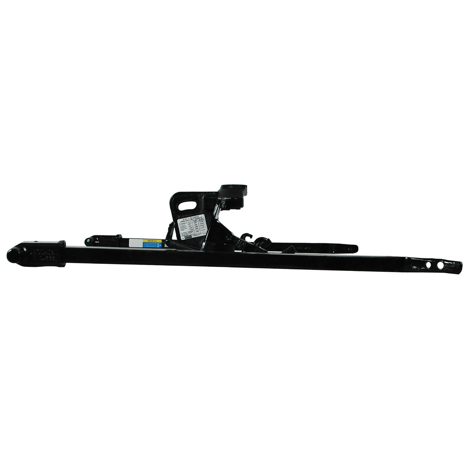
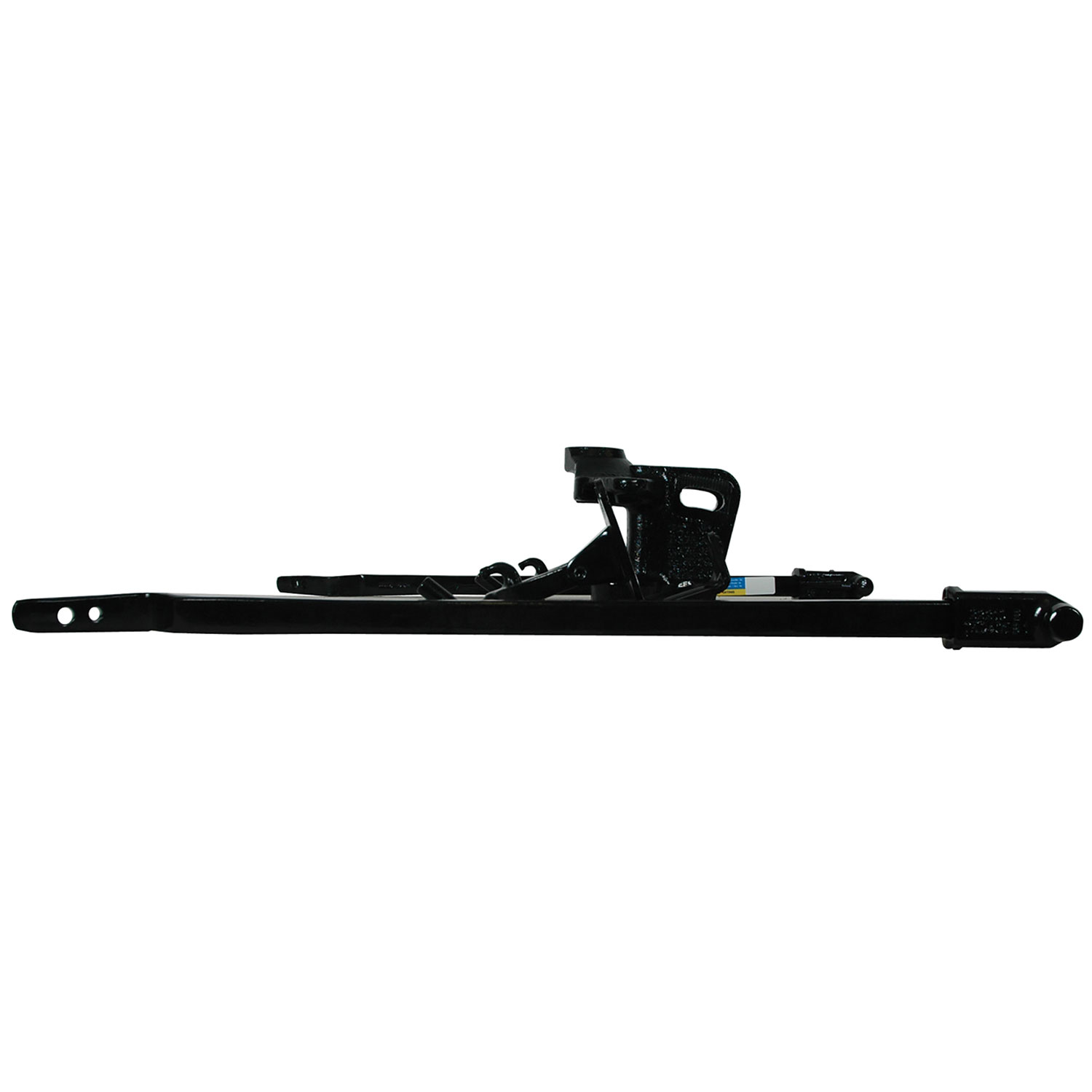
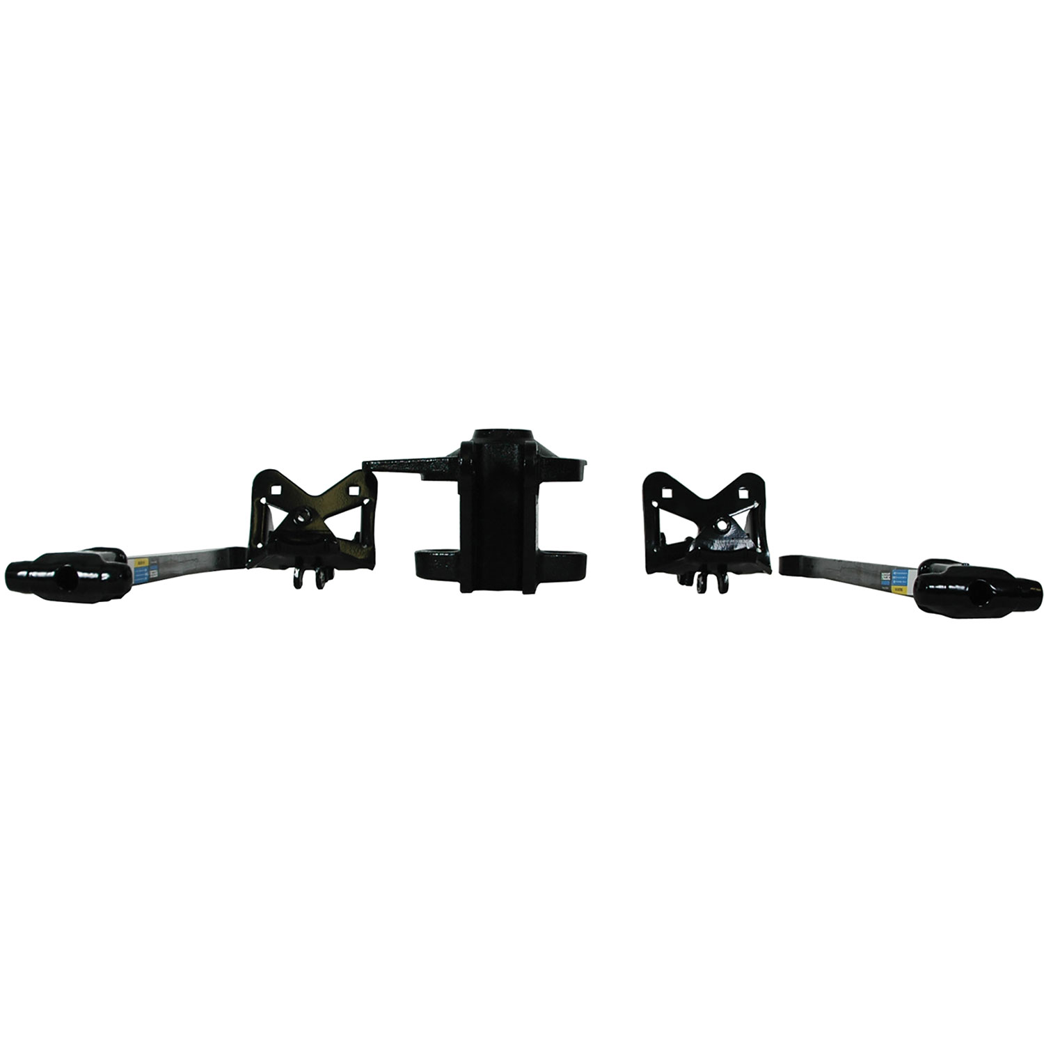
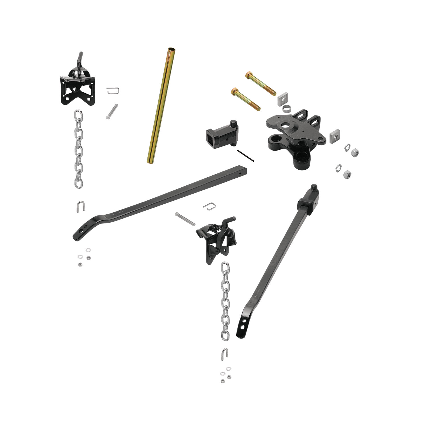
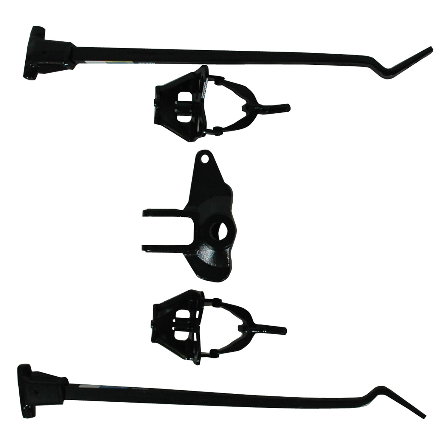
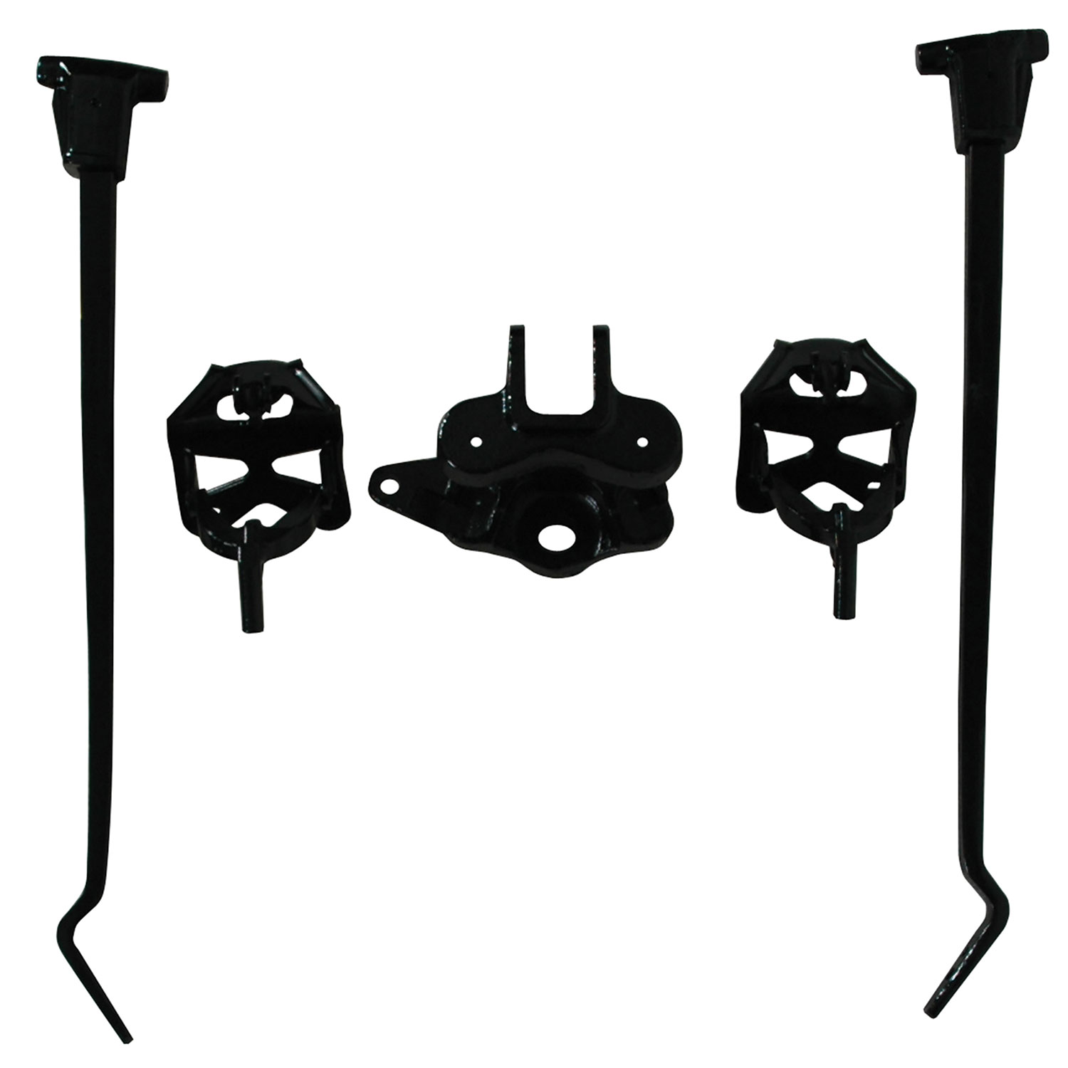
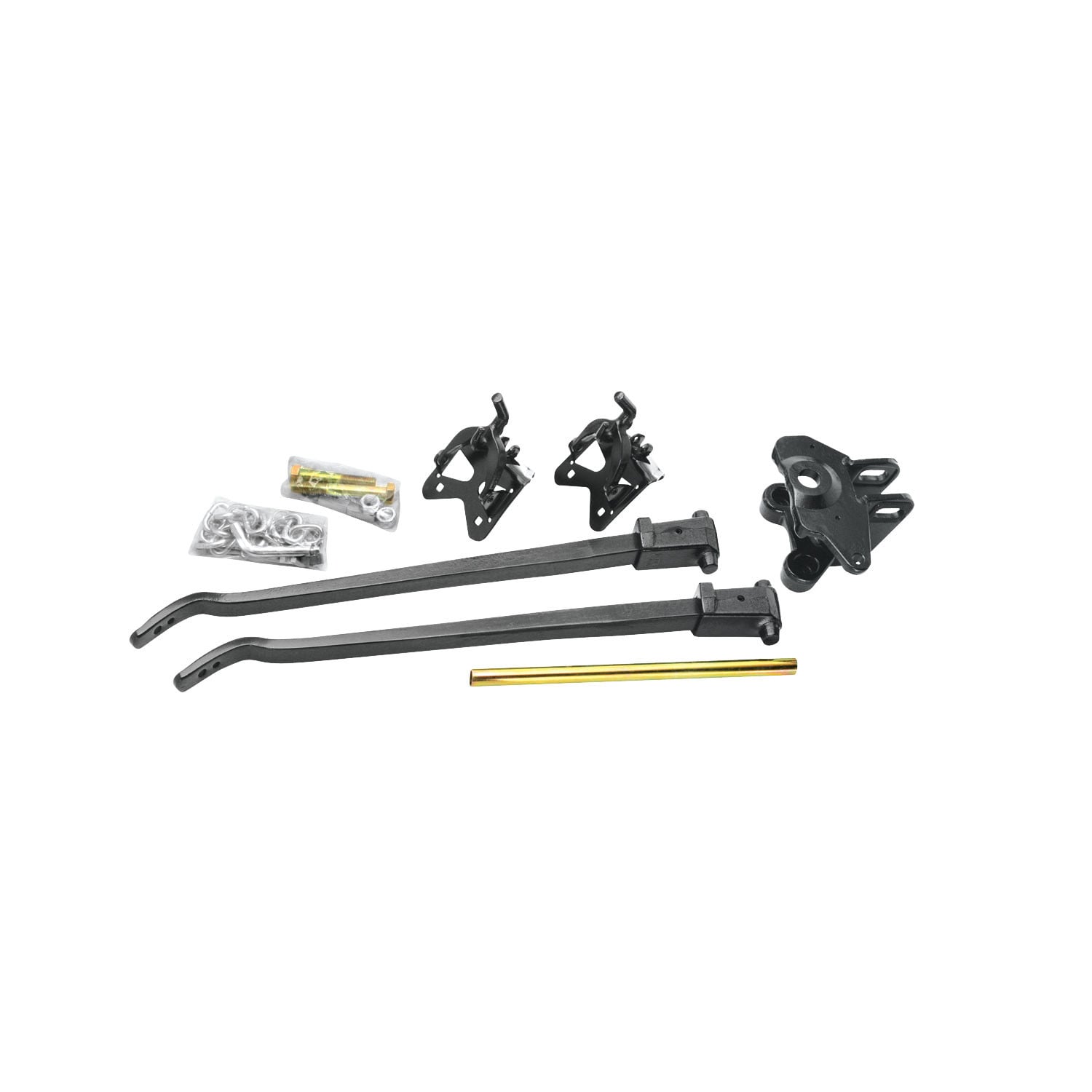
Reese has combined the best of the features from all of our weight distributing kits to create the High-Performance Trunnion Kit. It includes a head design with superior strength and easy adjustment.
| BRAND: | REESE |
| PART NUMBER: | 66021 |
| WARRANTY: | LIMITED LIFETIME WARRANTY |
| WEIGHT: | 59.1 LBS |
| CAPACITY: | 8,000 LBS. |
| GROSS TONGUE WEIGHT: | 800 LBS. |
| INCLUDES SWAY CONTROL: | NO |
| UNIVERSAL OR SPECIFIC FIT: | UNIVERSAL |
| LENGTH: | 31 IN. |
| SAFETY CHAINS INCLUDED: | NO |
| MATERIAL: | STEEL |
| MOUNTING HARDWARE INCLUDED: | YES |
| ADJUSTABLE ARMS: | YES |
| MOUNTING BRACKET POSITION: | 28 IN. |
| COLOR: | BLACK |
| BOLT GRADE: | GRADE 5 NUT & GRADE 8 BOLT |

Reese has designed towing equipment since 1952 and remains a benchmark for heavy-duty towing. The line covers fifth wheel hitches such as the modular M5, gooseneck couplers including the Goose Box, air-ride and short-bed pin boxes, weight distribution systems with active sway control, and the accessories that connect them, all built to exceed published industry standards.
Reese has been pioneering towing performance since 1952, when Margaret Reese asked her husband TJ to stop travel trailers rocking every time somebody walked through them. His answer, the first pair of stabilising jacks, was simple and effective enough to change the RV industry. From that starting point Reese grew into a designer and manufacturer of complete towing systems, and today it anchors the heavy-duty end of the Horizon Global towing portfolio.
Fifth wheel towing is where the brand's engineering is most visible. The M5 fifth wheel hitch uses a modular design that breaks into manageable sections for assembly, with a wider stance, tighter tolerances and a shock absorption system aimed at the jolts that travel up through a truck bed. For owners who would rather tow from a gooseneck coupler and keep the bed clear, the Goose Box 20K replaces the trailer's king pin with a gooseneck connection carrying its own air-ride cushioning.
Pin boxes are a Reese speciality. The 5th Airborne uses air-ride technology to dampen road shock and reduce the chucking motion that makes fifth wheel towing tiring, while the Sidewinder was designed for short-bed pickups, pivoting the connection point so the trailer can turn sharply without the front cap meeting the cab.
For conventional towing, Reese weight distribution systems restore load to the tow vehicle's front axle and control sway. The Pro Round Bar distributes weight evenly while damping sway, and the Pro Dual Cam II uses active cam-based sway control that works harder the stronger the sway force becomes. Complete kits pair bars, head and shank to a rated tongue weight, and dedicated sway control kits can be added to existing setups. The products suit RV owners, horse and livestock haulers and anyone towing near the upper end of a vehicle's rating.
Experts available to answer your questions
Call 888-634-9494Lifetime
Reese® and Pro Series™ Weight Distribution & Sway Control Hitches
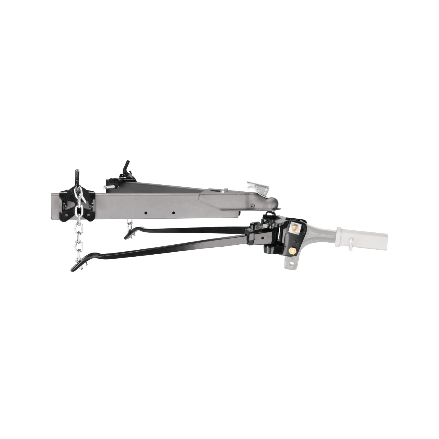
A trunnion style weight distributing hitch kit is a towing system that distributes the trailer's tongue weight across the towing vehicle's frame using spring bars and a ballmount head assembly. The trunnions (pivot points) allow the spring bars to move and adjust the load distribution, helping to maintain level vehicle and trailer attitude during towing and improving stability and braking.
The kit accepts hitch balls with three common coupler sizes: 1-7/8", 2", and 2-5/16". The ball must have a threaded shank of either 1-1/4" or 1" and be V-5 rated equal to or greater than the trailer's gross vehicle weight rating (GVWR). Standard height balls with 1-1/4" shanks are supplied with lock washers and nuts; if you must use a 1" shank ball, use bushing 58184 (B) to reduce the ballmount hole size to 1".
Raised balls usually have reduced load ratings. The ball rating must equal or exceed the trailer GVWR. If you use a raised ball, verify that its rating is sufficient for your trailer's weight; do not assume a raised ball has the same capacity as a standard height ball.
Some surge brakes are not compatible with weight distributing hitches. Check with the brake manufacturer before using this kit. Additionally, do not use sway control with surge brakes.
Yes, but you will need a pole tongue adapter. If your trailer has a straight tongue instead of an A-frame tongue, the adapter attaches to the trailer tongue and provides a place to attach the snap-up brackets.
No. Do not attempt to tow any type of trailer behind another trailer. Towing multiple trailers may cause severe instability, loss of control, and/or structural failure, and may result in vehicle accident, property damage, and personal injury. Towing multiple trailers is illegal in many jurisdictions.
You can install the hitch on a front-wheel-drive vehicle, but do not attempt to hook up or tow with the rear wheels removed. Severe structural damage to the towing vehicle, hitch, and trailer may result. A towing vehicle/trailer combination cannot be controlled adequately unless the towing vehicle's rear wheels are carrying their share of the load.
For the main hitch installation, you will need a wrench to torque the hitch ball nut and the high-performance ballmount nuts. For the optional snap-up bracket installation, you will need drill bits in sizes 7/16", 9/16", and 1/4", and a torque wrench capable of 50 ft/lbs and 300 ft/lbs.
The kit includes a ballmount (G), hitch bar (D, not included in all kits), spring bars with trunnions, snap-up brackets, chains with U-bolts and locknuts, lock washers, nuts, and a pull pin. Optional items include bushing 58184 (B) for 1" shank balls and shim kit 58207 for gap filling. The snap-up bracket installation kit includes 2 self-tapping screws (1/2" x 1.00") and an instruction sheet.
No. The hitch bar (D) is not included in all kits. Some installations may require a longer hitch bar if extended bumper guards, pickup truck caps, or rear-mounted spare tires limit turn angles. Individual hitch bars are available in various sizes.
1. Line up the tow vehicle and trailer on level pavement in a straight-ahead position, uncoupled. 2. Level the trailer and measure the distance from the ground to the top of the ball socket (X dimension). 3. For vehicles with air springs, air shocks, or automatic leveling systems, check the vehicle owner's manual. 4. Unless otherwise specified, level the vehicle with it loaded as it will be when towing before setting ball height and attaching the trailer. 5. Before final leveling, ensure the car and trailer are loaded and ready for travel.
Ball height should be greater than coupler height (measured in step 1 of Initial Set-Up) to compensate for vehicle squat, approximately 3/4" to 1" higher. The ballmount (G) is adjustable and can be positioned up or down on the hitch bar to achieve the correct height. Final ball height is confirmed after the spring bars are loaded and the front wheel well height is measured.
1. Select a hitch ball with a diameter matching the trailer coupler size (1-7/8", 2", or 2-5/16") and a threaded shank of 1-1/4" or 1". 2. Attach the ball to the ballmount (G). 3. Always use a lock washer and place it next to the nut. 4. Unless otherwise specified by the ball manufacturer, torque the ball nut to 450 ft/lbs for a 1-1/4" nut or 250 ft/lbs for a 1" nut. If using a 1" shank ball, use bushing 58184 (B) to reduce the ballmount hole size to 1".
1. Install hardware in the lower hole of the ballmount and tighten the nut enough to prevent easy rotation. 2. Determine the spring bar height "Y" using the table provided (based on coupler height X and coupler style A, B, or C). 3. Insert the spring bar and trunnion into the ballmount. 4. Swing the bar outward to the same angle as when connected to the trailer. 5. Lift up on the bar to remove slack. 6. Tilt the ballmount to achieve the proper Y dimension at the end of the spring bar. The ballmount is adjustable through a 15° angle range.
1. Install the longer 3/4" bolt (J) with two serrated washers (E) as shown in the diagram. 2. Install the lock washer (L) and nut (K), but allow space for the washers to be positioned and aligned. 3. Align the washers so the teeth are parallel and an equal number of teeth show at the top and bottom. 4. Hold the washers in position and tighten the nut. 5. Torque both nuts (K) to 300 ft/lbs. If a proper torque wrench is not available, torque the nuts to 150 ft/lbs, then turn them an additional 1/4 turn. 6. Do not lubricate the threads.
Use the shim provided when needed to fill any gap between the weight distributing head and the hitch bar used in your particular application. Install the shim from top down. If the shim goes all the way down to line up with the bottom hole, use the entire shim. If the shim does not fit between the head and hitch bar, discard it; the existing gap is acceptable. If the shim does not go far enough to reach the bottom hole, cut it in half and use only the top half for the top bolt; discard the bottom half. In rare cases where two shims are needed, contact Customer Service at 800-632-3290 or 800-428-7303 for a free additional shim service kit #58207.
Attach chains to the spring bars using U-bolts, flat washers, and locknuts. Let 2-3 threads protrude below the locknut. The chain must not bind. The procedure is the same for both standard spring bars and integrated cam spring bars.
1. Hold the spring bar away from you with the trunnion ribbed side up. 2. Set the bottom knob of the trunnion into the lower socket of the ballmount (G). 3. Slide the knob into the top slot of the ballmount. The spring bars will fit on either side as they are not made right or left handed.
1. Position the snap-up brackets on the trailer A-frame so that the chain at the end of the spring bar is approximately vertical. 2. Turn the 1/2 X 3-1/2 bolt until it contacts the frame. 3. Then tighten 1/4 turn with a wrench. Do not overtighten. 4. Raise the trailer tongue and rear of the car with a jack. 5. Lower the yoke of the snap-up bracket until it is parallel with the ground. 6. Slip the closest link over the hook. If there are fewer than 5 links between the hook and U-bolt, adjust the ballmount angle rearward and repeat the procedure. 7. With the snap-up bracket handle over the yoke, raise until the yoke has passed over-center. 8. Slide the safety pin through the small hole to lock the yoke in place. 9. Repeat for the other side.
1. Pick reference points on the front wheel well and measure the distance to the pavement before loading. 2. After the spring bars are loaded and the yoke is locked in place, lower the jack and re-measure the front wheel well reference point. 3. The front wheel well height should be equal to the original measurement. 4. If the front wheel well height is higher than originally measured, reduce the number of links between the yoke hook and spring bar (minimum 4 links) and recheck. 5. If the front wheel well is lower than originally measured, increase the number of chain links and recheck. 6. If the original wheel well height is not achievable, it is preferred that the wheel well height be lower after the spring bars are loaded. 7. If there are no more chain links for adjustment, the head assembly must be tilted forward: uncouple the trailer, remove the upper bolt from the head assembly, pivot the head up as appropriate, reassemble, and recheck the wheel well height.
Yes. If your snap-up bracket does not already have a hole in the required location, you must drill it. The hole must be drilled 2-1/4" above the arc in the bracket, centered left to right. Drill a 9/16" hole in the bracket before placing it on the frame. Then, using the bracket hole as a guide, drill a 1/4" pilot hole in the frame, staying centered. One method is to use the 9/16" drill bit first to make a small dimple in the frame, then finish with the 1/4" drill bit and then the 7/16" drill bit to get the final hole.
Yes. If the shim does not go far enough to reach the bottom hole, cut the shim in half and use only the top half for the top bolt. Discard the bottom half of the shim.
Unless otherwise specified by the ball manufacturer, torque the ball nut to 450 ft/lbs for a 1-1/4" nut or 250 ft/lbs for a 1" nut. Always use a lock washer and place it next to the nut.
Torque both nuts (K) to 300 ft/lbs. If a proper torque wrench is not available, torque the nuts to 150 ft/lbs, then turn them an additional 1/4 turn. Do not lubricate the threads.
Install the 1/2" self-tapping screw into the hole in the bracket and frame. Tighten it to 50 ft/lbs. Then re-tighten the 1/2" set screw on the inside of the frame, turning only 1/4 to 1/2 of a turn after making contact with the frame.
The spring bar height Y depends on your coupler height X and coupler style (A, B, or C). Refer to the table in the Preliminary Ballmount Adjustment section. For example, if your coupler height is 7", use Y = 7" for style A, 4-1/2" for style B, or 5-1/2" for style C. Add 1" to the Y dimension for non-integrated cam spring bars.
Yes. Always hook up trailer lights, turn signals, electric brakes, and break-away switch connection (if equipped) even for short trips. Ensure all electrical connections are in working order before towing.
Loaded ball height should never be greater than uncoupled ball height. If the loaded ball height is greater than the uncoupled height, front wheel overload and loss of rear wheel traction can result, leading to unstable handling, reduced braking ability, and a tendency to jackknife when turning and braking at the same time. If this occurs, reduce the take-up on spring bar chains and re-measure until proper height is obtained.
No. Trailers should not be occupied while being towed, under any circumstances.
If any part of your towing system bottoms out or if you suspect damage may have occurred in any other way, pull over and make a thorough inspection. Correct any problems before resuming travel. Severe bumps and badly undulating roads can damage your towing vehicle, hitch, and trailer, and should be negotiated at a slow steady speed.
Tongue weight should be about 10-15 percent of the gross trailer weight for most trailers. Too low a percentage of tongue weight will often produce a tendency to sway. Excess weight on the tongue can also lead to sway and damage the hitch and/or tow vehicle.
A sway control can help minimize the effects of sudden maneuvers, wind gusts, and buffeting caused by other vehicles. Use of a sway control is recommended for trailers with large surface areas, such as travel trailers. However, do not use sway control with surge brakes.
After loading the spring bars, check the following: 1. Verify that the trailer is level; if not, you may need to re-adjust the ballmount angle and/or position. 2. Verify that there is room for the bar and chain to move when turning a corner. 3. Confirm that the front wheel well height matches the original measurement (or is lower if the original cannot be achieved).
FALR stands for Front Axle Load Return. 100% FALR means the front fender is returned to the preload position. This is the recommended setting for best performance of the weight distributing hitch.
Trunnions should be lubricated each towing day. When hooking up, place one drop of oil on the top and a second drop on the forward side of the upper trunnion. Place a third drop on the rear side of the lower trunnion before inserting it into the ballmount. Use heavy oil or grease. It is not necessary to unhook the spring bars, as there are two oil holes in the ballmount top plate for upper trunnion lubrication. Lubricate lower trunnions with one drop at the contact point between trunnion and lower socket. Also lubricate the hitch ball with one or two drops.
At the beginning of every towing day: 1. Add a drop of oil at trunnion contact areas with the ballmount. 2. Clean the ball and coupler socket and coat the ball lightly with grease. 3. Check spring bar chains and U-bolts for wear; replace before they become worn halfway through. 4. Check that all bolts are properly tightened and the hitch pin and clip are securely in place. 5. Check that electrical hookups are in working order and that safety chains are connected.
1. Lubricate the ballmount sockets and spring bar trunnions to prevent rapid wear. 2. Keep trunnions and sockets in the head assembly free of dirt and well lubricated. 3. Keep the head assembly exterior clean, especially the trunnion sockets; do not allow dirt or stones to lodge between trunnions and head. 4. Wipe out excess oil, dirt, and grit whenever the trailer is uncoupled. 5. Keep the hitch painted to prevent rust and maintain a good appearance (do not paint over labels). 6. Remove the hitch from the towing vehicle receiver when not towing to prevent contamination of head sockets, reduce the chance of striking the hitch on driveway ramps or other objects, and minimize damage in the event of a rear-end collision.
Excessive wear in the trunnion and socket area may indicate overload or inadequate lubrication. Some elongation of socket openings (seat-in) is normal. Keep trunnions and sockets free of dirt and well lubricated to prevent excessive wear.
Unless specified otherwise by the towing vehicle or trailer manufacturer, tires should be inflated to their maximum recommended pressure.
This kit fits trailers with A-frame or pole tongue couplers in sizes 1-7/8", 2", or 2-5/16". The hitch ball must be V-5 rated equal to or greater than your trailer's GVWR. Check your trailer's coupler size and GVWR before purchasing.
You will need a wrench for torquing the hitch ball nut and ballmount nuts. For snap-up bracket installation, you will need drill bits (7/16", 9/16", 1/4") and a torque wrench capable of 50 ft/lbs and 300 ft/lbs.
The manual does not mention disconnecting the battery. This is a mechanical hitch installation with no electrical components to the hitch itself, though you will need to connect trailer lights and brakes separately.
Drilling is required only if you are installing the optional snap-up bracket and your bracket does not already have a hole in the required location. You will drill a 9/16" hole in the bracket and a 1/4" pilot hole in the trailer frame, then a 7/16" final hole.
Torque both nuts to 300 ft/lbs. If a torque wrench is not available, torque to 150 ft/lbs then turn an additional 1/4 turn. Do not lubricate the threads.
Lubricate the trunnions and ballmount each towing day before hooking up. Place one drop of oil on the top and forward side of the upper trunnion, and one drop on the rear side of the lower trunnion. Use heavy oil or grease.
Loaded ball height must never exceed uncoupled ball height. If it does, you risk front-wheel overload, loss of rear traction, and jackknifing. Adjust the spring bar chain length to correct this before towing.
Reduce the number of links between the yoke hook and spring bar (minimum 4 links) and recheck the wheel well measurement. If the height is still too high, continue reducing links. If you cannot achieve the original height and there are no more chain links for adjustment, the head assembly must be tilted forward: uncouple the trailer, remove the upper bolt from the head assembly, pivot the head up as appropriate, reassemble, and recheck the wheel well height.
Increase the number of chain links between the yoke hook and spring bar and recheck the wheel well measurement. If the original wheel well height is not achievable, it is preferred that the wheel well height be lower after the spring bars are loaded, as long as there is adequate clearance.
If there are fewer than 5 links between the hook and U-bolt when the yoke is positioned parallel to the ground, adjust the ballmount angle rearward and repeat the snap-up bracket positioning procedure. This adjustment changes the geometry to provide the correct number of links.
If the serrated washers are not aligned parallel with the teeth on the ballmount, and an equal number of teeth do not show at the top and bottom, the teeth can be stripped when loaded. Always align the washers correctly and re-check the alignment after tightening the nut.
If the shim will not begin to fit between the head and hitch bar, discard the shim and continue the installation. The existing gap is acceptable.
If the shim does not go far enough to reach the bottom hole, cut the shim in half and use only the top half for the top bolt. Discard the bottom half of the shim.
If the trailer is not level after loading the spring bars, you may need to re-adjust the ballmount angle and/or position. Refer to the Preliminary Ballmount Adjustment section and the Initial Hook Up section to verify that the spring bar height (Y) is correct for your coupler height and that the snap-up bracket positioning is correct.
The chain must not bind. When attaching chains to the spring bars using U-bolts, flat washers, and locknuts, ensure that 2-3 threads protrude below the locknut and that the chain is positioned so it does not interfere with the spring bar movement.
Free Shipping
Ships free on all orders
 Authorized Dealer

Quick Ship
In stock and ready to ship — order now!
FREE ShippingFREE SHIPPING
Estimated delivery Thu, Sep 17 - Sun, Sep 20
Order before 2 PM EST Monday–Friday for same-day processing
Guaranteed safe & secure checkout
Sam
Ordered online. Shipment arrived on time and with all the correct parts. Great customer service and friendly staff. Also, pricing was great!
May 22, 2023