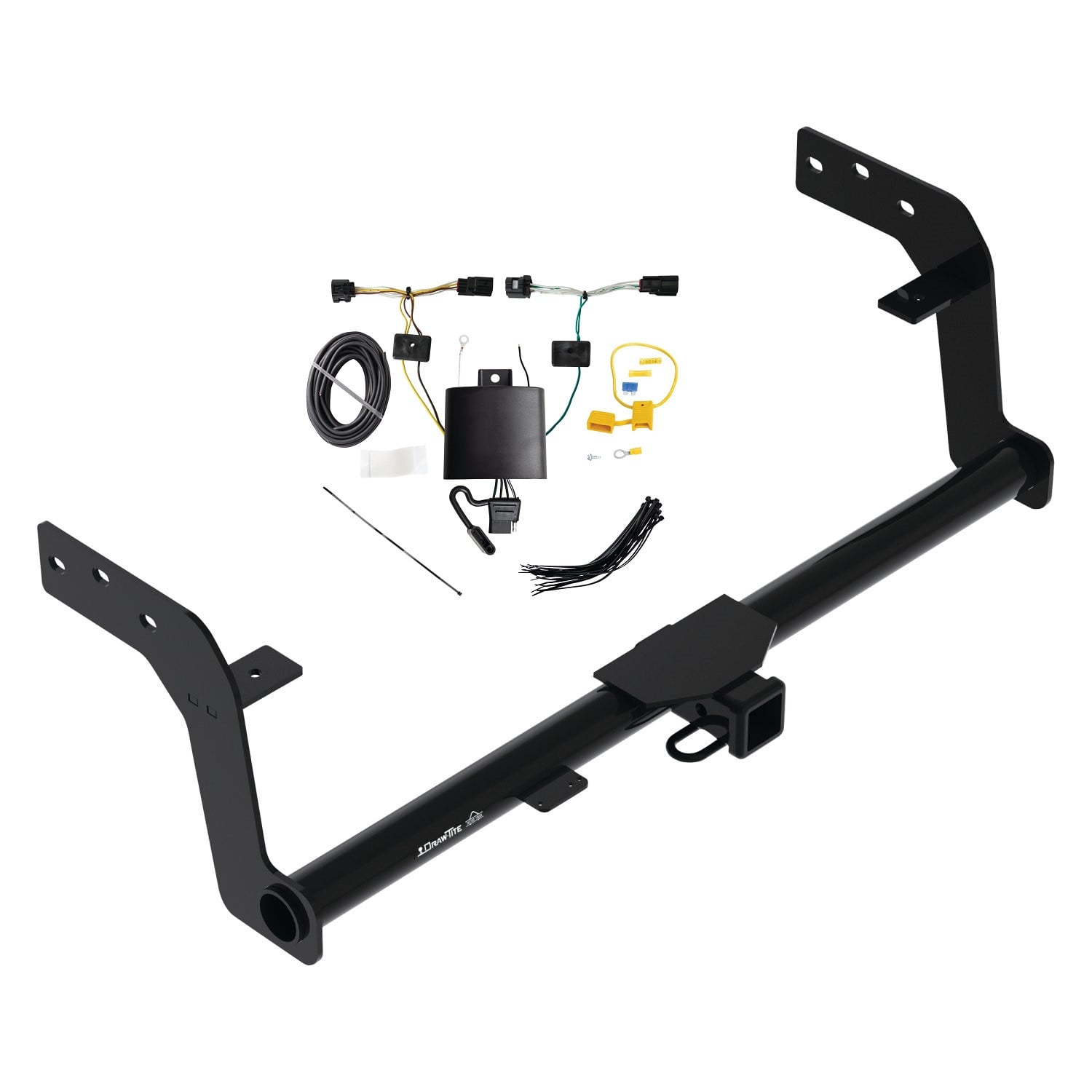
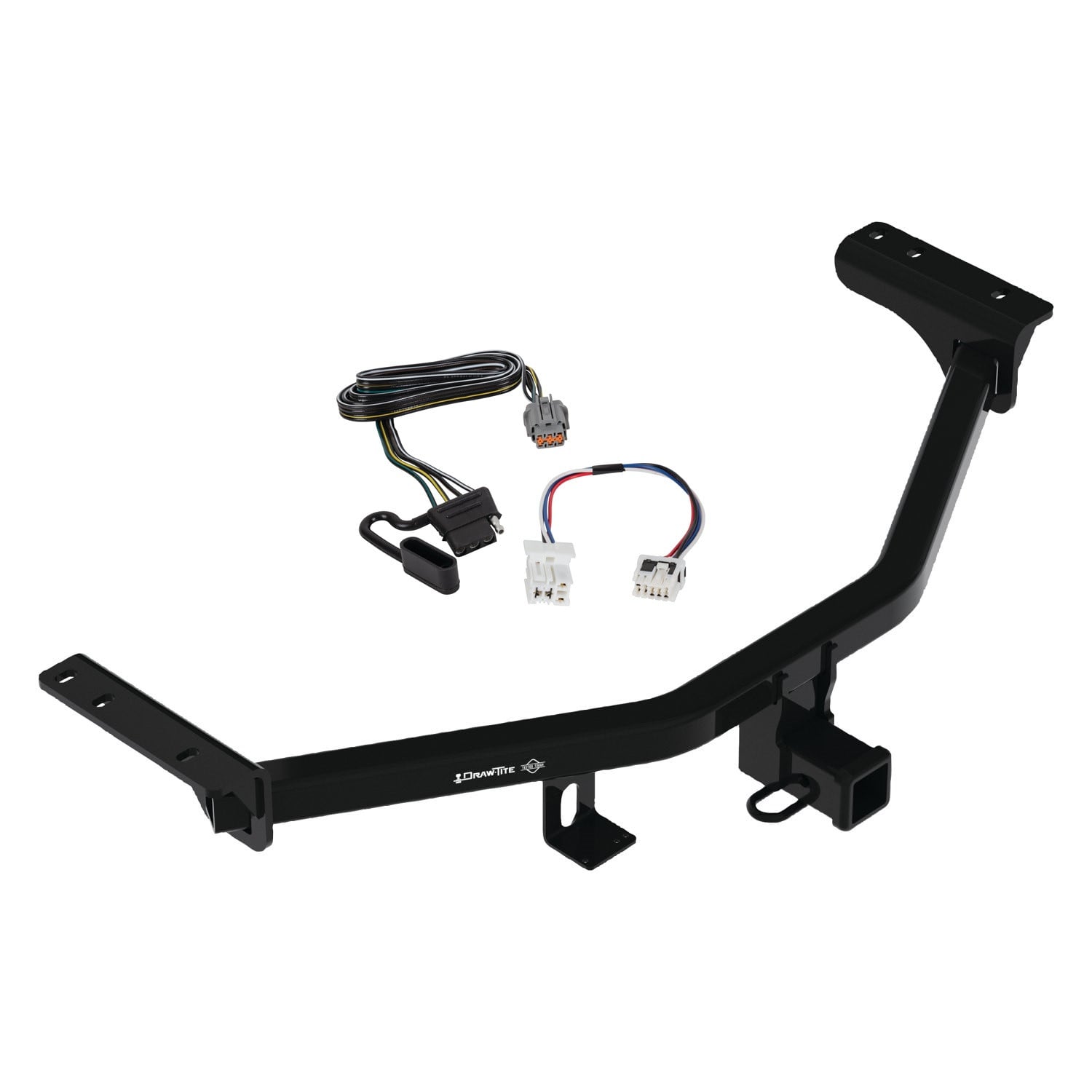
2022-2024 KIA Carnival Draw-Tite Class 3 Trailer Hitch, 2 Inch Square Receiver Bundle w/ Plug-n-Play T-One Wiring HarnessDraw-titeOriginal price was $388.75. Current price is $367.56.Out of Stock
View productOur in-house experts typically reply within one business day.

Draw-tite
Verify Fitment
Select your vehicle to confirm this part fits.
2022 - 2024 Genesis GV70
Confirmed to Fit


Always the correct part
We know our products
Quality Products
Free Shipping!
Always the correct part
We know our products
Quality Products
Free Shipping!
On Sale Today
Original price was $503.75. Current price is $493.57.You save $10.18
Free Shipping
Ships free on all orders
 Authorized Dealer

FREE ShippingFREE SHIPPING
Estimated delivery Thu, Sep 17 - Sun, Sep 20
Order before 2 PM EST Monday–Friday for same-day processing
Guaranteed safe & secure checkout

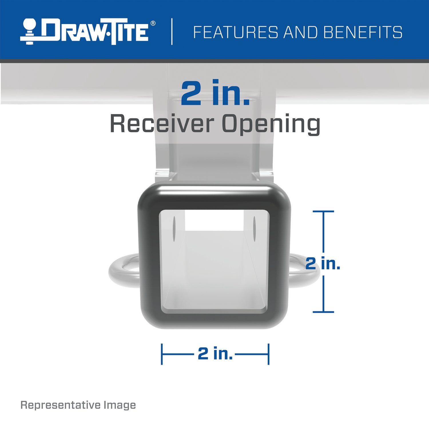
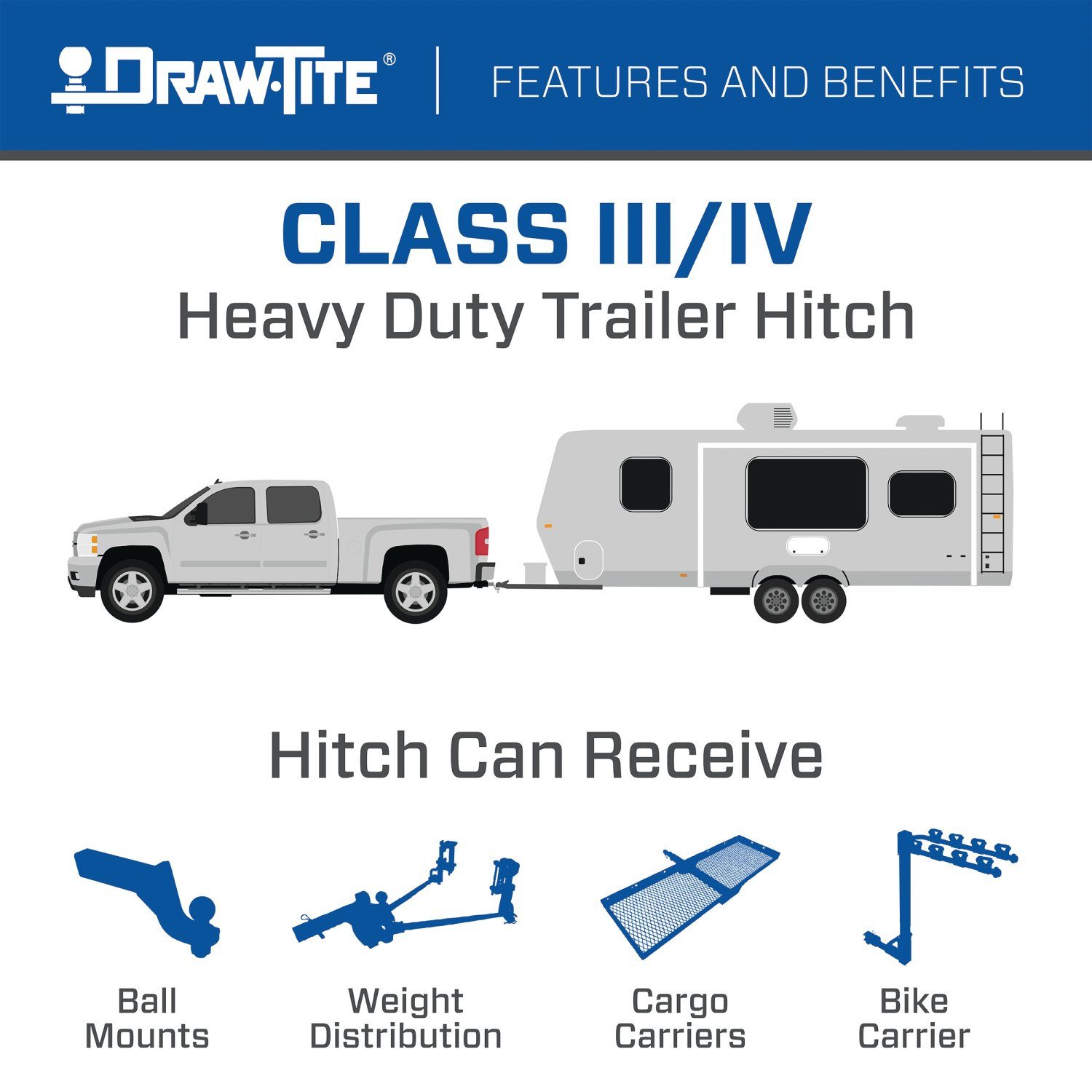
These durable custom hitches are manufactured for 2022-2023 Genesis GV70 and attach to your vehicle?s frame or bumper for a sleek, clean appearance. Each hitch also has a 2 inch square receiver tube opening ? the most common and versatile on the market - allowing you to attach accessories like a bike rack or cargo carrier, or hook up your pop-up, boat trailer, or utility trailer. The options are endless! DRAW-TITE Class 3 Custom Trailer Hitches come complete with all the mounting hardware needed for installation and are backed by a nationwide lifetime limited warranty. So, whether you are headed out to the campground, the lake, or the bike trails, or you are tackling a project at home and need to haul the materials home, choose DRAW-TITE and travel with confidence knowing your setup is connected with the security only DRAW-TITE can provide. DRAW-TITE: North America?s Favorite Hitch

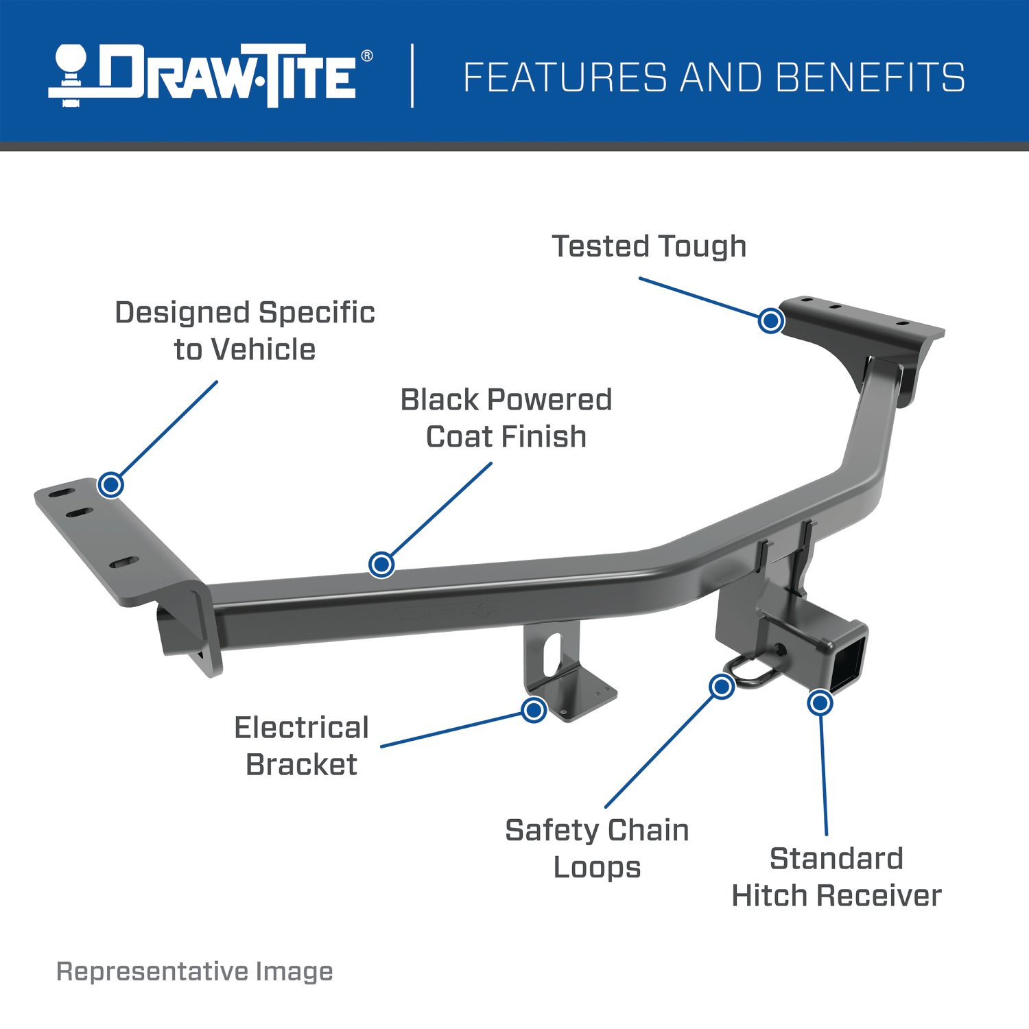
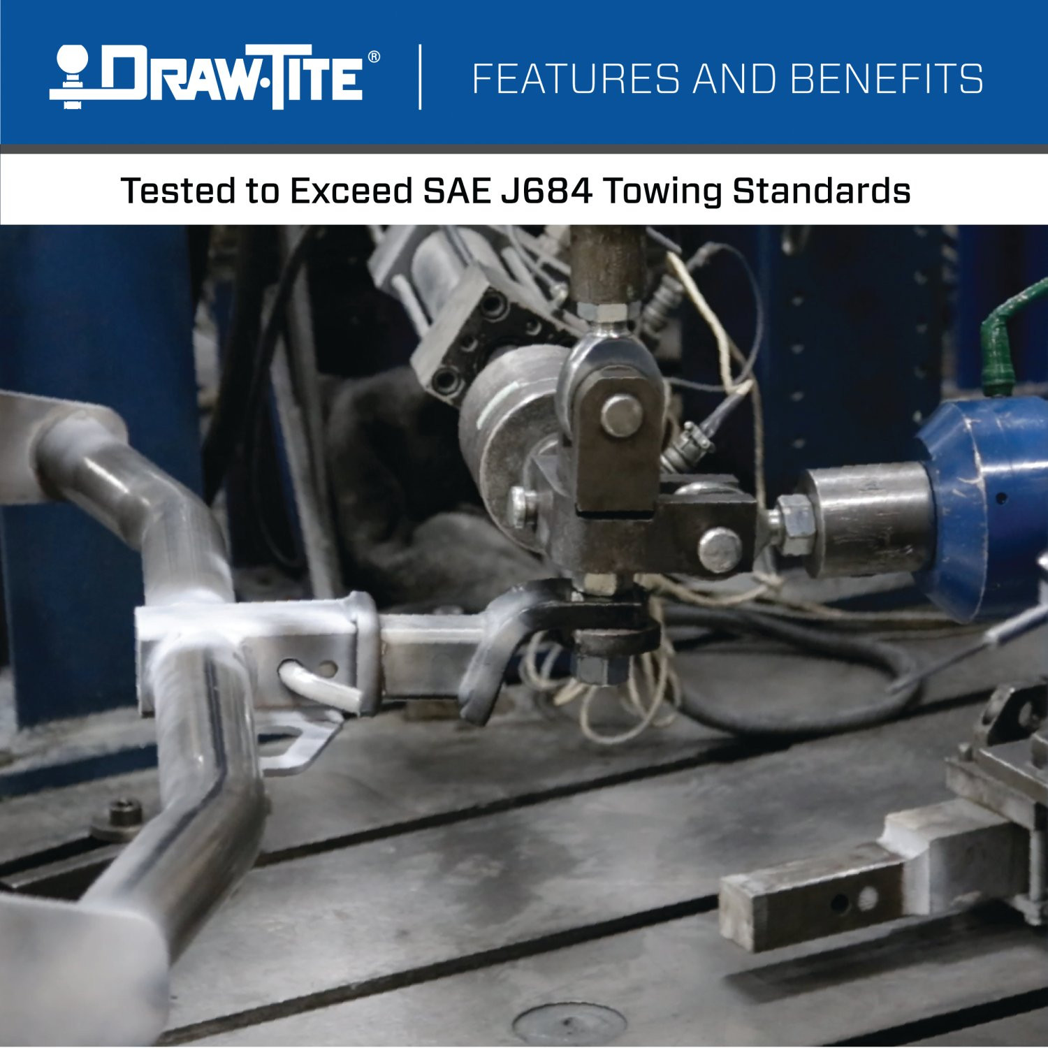
Draw-Tite has designed custom-fit trailer hitches since 1946 and is one of North America's most widely fitted hitch brands. Receiver hitches use solid all-welded construction and low-profile designs that follow modern vehicle contours, install with minimal bumper cutting or drilling, meet or exceed V5 CSA and SAE J684 standards, and carry a limited lifetime warranty.
Draw-Tite has been leading custom-fit trailer hitch design and engineering since its founding in 1946, and it remains one of the most widely fitted hitch brands in North America. The company's stated approach is straightforward: every hitch is tested rigorously so that it performs well beyond published industry standards, a philosophy it markets as Tested Tough. It sits within the Horizon Global towing group alongside Reese, Fulton, Bulldog, Tekonsha, Bargman and Wesbar.
Custom fit is the defining characteristic. Rather than adapting a universal design, Draw-Tite engineers a trailer hitch for a specific make, model and model year, so it bolts to existing frame locations with minimal bumper cutting or drilling. Low-profile designs follow the rear contours and aerodynamic styling of modern vehicles, which matters more than it once did now that rear fascias are shaped and sensor-equipped. Construction is solid all-welded steel for maximum strength, and every hitch meets or exceeds V5 CSA and SAE J684 standards and is backed by a nationwide limited lifetime warranty.
The range spans receiver sizes and classes to suit different loads, from 1-1/4 inch receivers for bike racks, cargo carriers and light trailers up through 2 inch receivers for heavier towing. Front mount hitches add a receiver at the front of the vehicle for winch mounts, snow plows, spare carriers and precise trailer positioning.
The Hidden Hitch series takes concealment further by mounting behind the vehicle's rear fascia, so the vehicle keeps its factory appearance until a removable receiver is fitted. Each is custom designed per make and model for a no-drill installation that does not compromise ground clearance, rated for up to 3,500 pounds gross trailer weight and 350 pounds tongue weight. Matching plug-and-play wiring completes the towing system.
Experts available to answer your questions
Call 888-634-94941 compatible vehicles
| Year | Make & Model | Notes |
|---|---|---|
| 2022 - 2024 | Genesis GV70 | — |
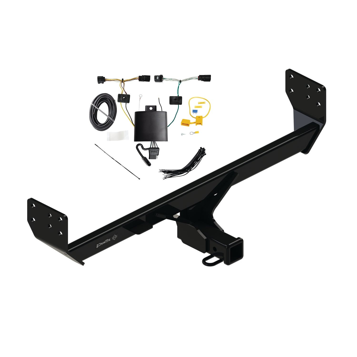
The 2022-2024 Genesis GV70 Draw-Tite Class 3 Trailer Hitch, 2 Inch Square Receiver Bundle w/ Plug-n-Play T-One Wiring Harness (Part #DTB76577-118851) fits the following vehicles: 2022-2024 Genesis GV70. Always verify your specific year, make, and model before ordering.
The 2022-2024 Genesis GV70 Draw-Tite Class 3 Trailer Hitch, 2 Inch Square Receiver Bundle w/ Plug-n-Play T-One Wiring Harness (Part #DTB76577-118851) fits 2022-2024 Genesis GV70 models. The 2024 model year is the last year covered by this part number. For newer models, check for an updated version.
Yes, the 2022-2024 Genesis GV70 Draw-Tite Class 3 Trailer Hitch, 2 Inch Square Receiver Bundle w/ Plug-n-Play T-One Wiring Harness (Part #DTB76577-118851) is designed to fit the 2022-2024 Genesis GV70.
The 2022-2024 Genesis GV70 Draw-Tite Class 3 Trailer Hitch, 2 Inch Square Receiver Bundle w/ Plug-n-Play T-One Wiring Harness (Part #DTB76577-118851) Refer to the included instructions for installation details. Basic hand tools are typically all you need.
Yes. Part numbers 76577, 84577, and CQT76577 are designed for 2022-current Genesis GV70 models. Visit the manufacturer's website for the most up-to-date information regarding specific application years and trim levels.
The maximum gross trailer weight is 3500 lb (1587 kg) and the maximum tongue weight is 525 lb (238 kg) for the weight-carrying version. Do not exceed the lower of your towing vehicle manufacturer's rating or these limits.
Required tools include: ratchet, torque wrench, sockets (11/16" and 19 mm), 6" socket extension, safety glasses, drill with ½" drill bit, die grinder, wire brush, flat head screwdriver, exhaust hanger removal pliers, marker, and soapy water or lubricant. Professional installation is recommended if you are not comfortable performing the work yourself.
Yes. The exhaust must be lowered before installation. Using a flat head screwdriver, remove 6 plastic rivets from the bottom of the fascia on both the passenger and driver sides. Using an exhaust hanger removal plier, remove 1 rearmost rubber hanger per side. Spray lubricant or soapy water on the rubber hangers to make removal easier. Lower the exhaust mufflers by gently pulling the lower fascia. Ensure the exhaust is properly supported before removing the rubber hangers.
Yes. Drilling is required. You must drill ½" holes in the frame rails at marked locations on both sides. After drilling, use a die grinder to enlarge the holes to accommodate the feed blocks into the vehicle frame rails. The holes are marked by positioning the hitch with spacer plates and using a marker to mark the drill point at the bottom frame rails based on the hitch bracket hole center.
Drill a ½" (0.5 inch) hole at the marked location on each side of the frame rails. After drilling, use a die grinder to enlarge the holes to feed the blocks into the vehicle frame rails. The enlargement area is shown in Figure 2 with dimensions of 1⅛" by ¼".
All M12 X 1.25 X 65 fasteners must be tightened to 76 ft.lb. (103 N·m) using a torque wrench. Proper torque is critical to keep the hitch securely mounted to the vehicle when towing.
All 7/16-14 X 1.50 fasteners must be tightened to 50 ft.lb. (68 N·m) using a torque wrench. Proper torque is critical to keep the hitch securely mounted to the vehicle when towing.
The fastener kit 76577F1 includes: (2) carriage bolts 7/16-14 X 1.50 GR5, (2) blocks 3/16 X 1.00 X 2.00, (2) conical washers 7/16, (2) nuts 7/16-14, (6) bolts M12 X 1.25 X 65 CL10.9, (6) conical washers ½, and (2) pull wires 7/16. Spacer plates are also provided with the hitch.
The teeth side of the conical washer must be against the hitch. This applies to both the conical washers ⑥ (½ size) installed on the M12 bolts at the hitch, and the conical washers ③ (7/16 size) installed on the carriage bolts.
The carriage bolts ① and blocks ② are fed through the drilled holes using the pull wires ⑦. Pull the bolts through the blocks using the pull wires. Leave the pull wires attached. Raise the hitch into position and feed the pull wires through the bracket bottom holes. Then loosely install the spacer plates, conical washers, and bolts to the hitch before removing the pull wires.
Always wear safety glasses when installing the hitch. Observe safety precautions when working beneath a vehicle and wear eye protection. Do not cut access or attachment holes with a torch. Ensure the exhaust is properly supported before removing rubber hangers. If the hitch is removed, plug all holes in the trunk pan or other body panels to prevent entry of water and exhaust fumes.
Check the hitch frequently to ensure all fasteners and the ball are properly tightened. Verify that the hitch is securely mounted to the vehicle. If the hitch is removed at any time, plug all holes in the trunk pan or other body panels to prevent entry of water and exhaust fumes. A hitch or ball that has been damaged should be removed and replaced.
Slow down when towing and never exceed any posted speed limit. If excess sway occurs, take your foot off the gas pedal and hold the steering wheel as steady as possible. Do not apply your brakes and do not speed up.
Load the trailer heavier in front. This helps with proper weight distribution and towing stability.
No. Do not cut, weld, or modify this receiver. Any modifications will compromise the structural integrity and safety of the hitch.
Check all fasteners periodically to ensure they are tight and the hitch is securely mounted to your vehicle. The manual does not specify an exact interval, but regular inspection before towing is recommended.
Yes, part numbers 76577, 84577, and CQT76577 fit 2022-current Genesis GV70 models. Check the manufacturer's website for the most current trim level information.
Maximum gross trailer weight is 3500 lb (1587 kg) and maximum tongue weight is 525 lb (238 kg). Do not exceed the lower of your vehicle manufacturer's rating or these limits.
Yes. You must drill ½" holes in the frame rails and use a die grinder to enlarge them. The exhaust must also be lowered before installation.
Required tools: ratchet, torque wrench, sockets (11/16" and 19 mm), 6" socket extension, safety glasses, ½" drill bit, drill, die grinder, wire brush, flat head screwdriver, exhaust hanger removal pliers, marker, and soapy water.
M12 X 1.25 X 65 bolts: 76 ft.lb. (103 N·m). 7/16-14 X 1.50 carriage bolts: 50 ft.lb. (68 N·m). Use a torque wrench for proper installation.
Always wear safety glasses. Ensure exhaust is properly supported before removing hangers. Do not cut holes with a torch. Observe safety precautions when working beneath the vehicle. Plug all holes if the hitch is removed.
Check all fasteners to ensure they are tight. Retighten M12 X 1.25 X 65 bolts to 76 ft.lb. (103 N·m) and 7/16-14 X 1.50 bolts to 50 ft.lb. (68 N·m) using a torque wrench. The manual recommends checking fasteners periodically to maintain secure mounting.
A hitch or ball that has been damaged should be removed and replaced. Do not attempt to repair or continue using a damaged hitch, as this compromises safety when towing.
The T-One® Connector is a trailer wiring harness connector system that integrates with your vehicle's existing tail light wiring to provide trailer lighting control. It uses a black module mounted underneath the vehicle and connects to both driver's and passenger's side tail lights via yellow and green wires, allowing your vehicle to control trailer lights when towing.
The manual shows installation on a Hyundai Genesis. However, the manual does not specify model years, body styles, cab configurations, or whether it fits other vehicles. Contact the manufacturer or check the product listing to confirm fitment for your specific vehicle.
You will need: trim panel remover, 10 mm socket and ratchet or 10 mm wrench, drill with 3/32" drill bit, wire crimpers, wire cutters, Phillips head screwdriver, and a test probe. A utility knife is also needed to slit the floor pan grommet. A fish wire is recommended (not required) to help route the harness through tight spaces.
The kit includes: two T-One® Connector ends (yellow and green wire), a black module box, double-sided tape for mounting, a white ground wire with eyelet and screw, a yellow fuse holder with 15 amp fuse, two yellow butt connectors, and a black 12 gauge power wire. All fasteners and connectors needed for installation are provided.
Yes. You must disconnect the vehicle's negative (−) battery cable before connecting the power wire to the positive (+) battery terminal. This is done in step 10 after routing the black 12 gauge wire from the module to the battery. Reconnect the negative cable only after the fuse is installed in step 13.
Yes. You must remove the trim panels covering the tail lights, then use a 10 mm socket to remove the mounting screws from both driver's and passenger's side tail lights. Be careful not to break the trim panel mounting tabs. The tail lights are then disconnected and set aside during installation.
Yes. In step 9, you must remove the threshold and cargo tray from the rear cargo area to access the battery. These items are reinstalled in step 14 after the electrical connections are complete.
Drilling may be required. You must drill a 3/32" hole to secure the white ground wire using the provided eyelet and screw, unless a suitable existing ground stud is available near the connector. You must also use a utility knife to slit the floor pan grommet in the rear cargo area to route the black 12 gauge power wire underneath the vehicle. Do not drill into the vehicle floor or bed.
No. You must locate a suitable grounding point near the connector, such as an existing ground stud. If you need to drill, you may drill a 3/32" hole, but you must not drill into the vehicle floor or bed. Before drilling, verify what is behind the surface to avoid damage to the vehicle and personal injury. Clean dirt and rustproofing from the area before securing the white ground wire.
The T-One® Connector uses a 15 amp fuse. The fuse is installed in the yellow fuse holder provided in the kit and is connected to the vehicle's positive (+) battery cable. The fuse must be installed in step 13 after all other electrical connections are complete.
The black power wire connecting the module to the battery is 12 gauge (12 ga.). The white ground wire is also included but its gauge is not specified in the manual. The yellow and green wires connecting to the tail lights are part of the T-One® Connector ends and their gauge is not specified.
The yellow wire connects to the driver's side tail light connector. The green wire connects to the passenger's side tail light connector. These wires allow the module to receive tail light signals from the vehicle. The white wire provides a ground connection near the module. The black 12 gauge wire carries power from the vehicle's positive battery terminal to the module.
Route the yellow wire harness from underneath the vehicle up through the opening between the rear bumper and body to the driver's side tail light pocket. Route the green wire harness similarly to the passenger's side tail light pocket. Route the black 12 gauge power wire from the module through the slitted floor pan grommet in the rear cargo area underneath the vehicle to the battery. The manual recommends using a fish wire between the tail light pocket and rear fascia to help pull the harnesses through tight spaces.
Mount the black module box underneath the vehicle behind the rear bumper fascia on the passenger's side using the double-sided tape provided. The epoxy side of the module must be pointed toward the ground to prevent water buildup. Ensure the mounting surface is clean and suitable for the adhesive.
Always wear safety glasses during installation. Before drilling, verify what is behind any surface to avoid damage to the vehicle and personal injury. Do not drill into exposed surfaces. When routing wires through grommets or along the exterior, avoid hot pipes, heat shields, the fuel tank, and any other points that may pinch or break the wire. Do not break trim panel mounting tabs or connector locking tabs. Read and follow all warnings printed on the vehicle's battery. Do not exceed the stated product ratings or the towing manufacturer's rating.
When routing wires through a grommet or along the exterior of the vehicle, carefully avoid hot pipes, heat shields, the fuel tank, and any other points that may pinch or break the wire. Do not route wires where they can be damaged by moving parts or sharp edges. Secure all loose wires and mount the trailer tow harness in an accessible location with a bracket or electrical box after installation.
After installation is complete, test and verify the installation with a test light or by connecting an actual trailer. For the initial test, reset the vehicle's electrical system by temporarily removing the key from the ignition. All connections must be complete for the T-One® Connector to function properly. If the system does not work, check that all wires are properly connected and the 15 amp fuse is installed.
After installation, verify that all trim panels, threshold, storage covers, and floor coverings are reinstalled without pinching or cutting any wires. Ensure all loose wires are secured and the trailer tow harness is mounted in an accessible location with a bracket or electrical box. Confirm that the module's epoxy side is pointed toward the ground. Test the system with a test light or trailer to verify proper function. Check that the 15 amp fuse is installed and the negative battery cable is reconnected.
The manual does not specify any regular maintenance intervals or procedures. However, it recommends optionally applying a small amount of silicone sealant to the floor pan grommet and wire after installation to prevent environmental intrusion. Ensure all connections remain clean and free of dirt, and periodically verify that the module remains securely mounted and that all wires are intact and properly routed.
The manual shows installation on a Hyundai Genesis, but does not specify model years or other vehicles. Check the product listing or contact the manufacturer to confirm fitment for your specific vehicle.
Yes, disconnect the negative (−) battery cable before connecting the power wire to the positive (+) terminal in step 10. Reconnect only after the 15 amp fuse is installed in step 13.
The black power wire connecting the module to the battery is 12 gauge (12 ga.).
Avoid hot pipes, heat shields, fuel tank, and pinch points. Do not route wires where they can be damaged. Secure all loose wires after installation.
Verify that all connections are complete and secure. Check that the 15 amp fuse is installed in the yellow fuse holder. Ensure the negative (−) battery cable is reconnected. Test the system with a test light or trailer. Reset the vehicle's electrical system by temporarily removing the key from the ignition. Verify that all connector surfaces are clean and free of dirt, and that the yellow and green wires are properly locked into the vehicle's tail light connectors.
The module is mounted with the epoxy side pointing upward instead of toward the ground. Remount the module so that the epoxy side is pointed toward the ground to prevent water buildup. Use the double-sided tape provided to secure the module in the correct orientation underneath the vehicle behind the rear bumper fascia on the passenger's side.


Total for 4 items:
$134.54$137.05
No reviews have been added for this product.