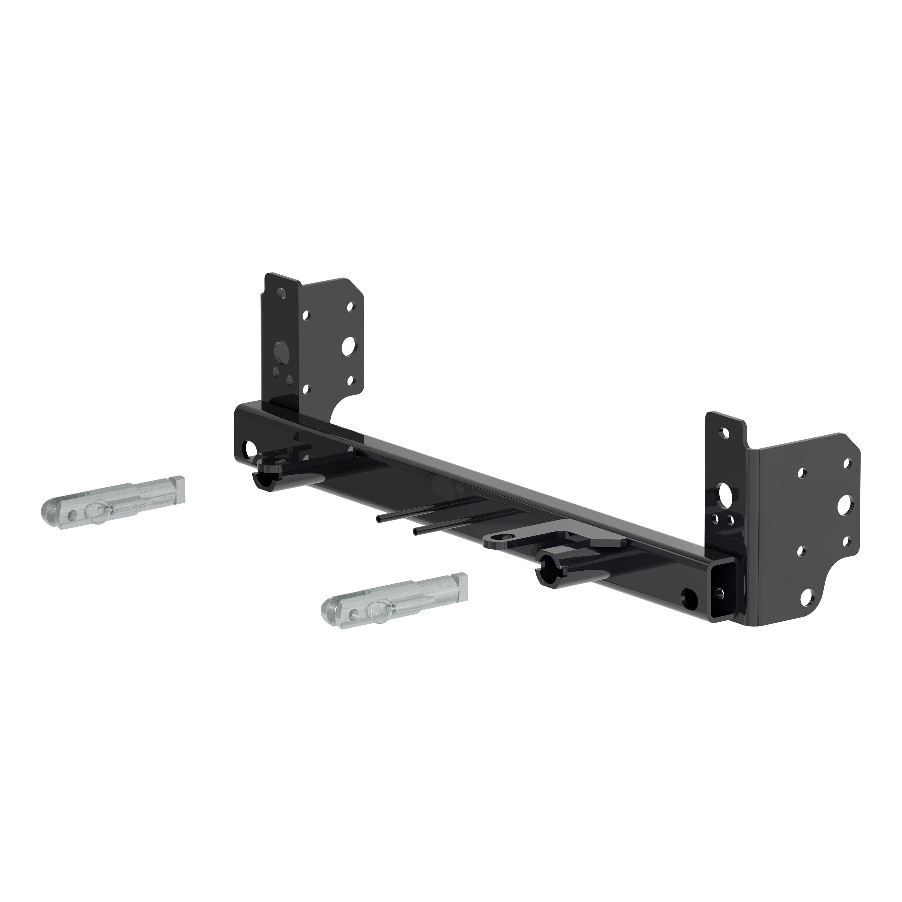
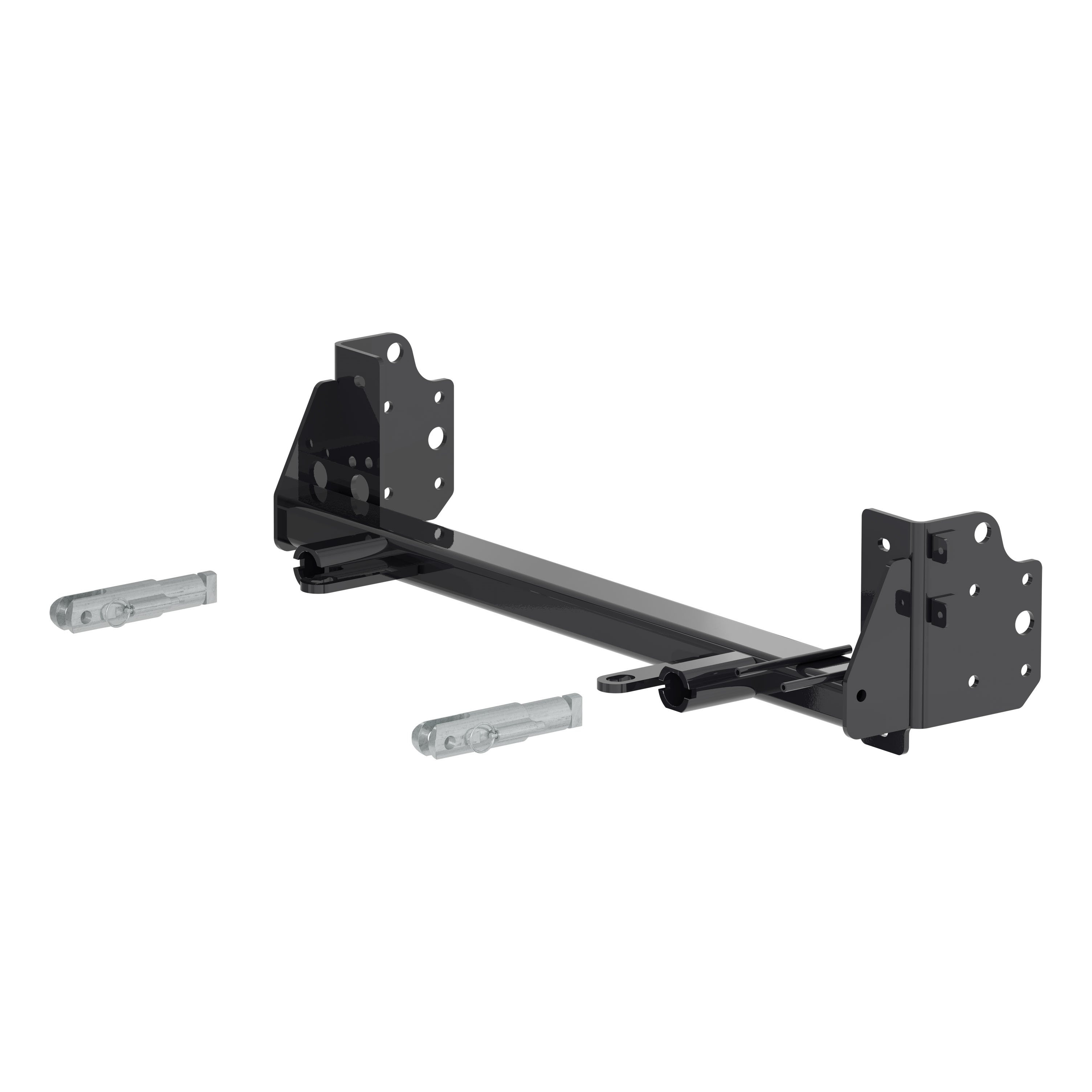
CURT 70152 Custom Tow Bar Base Plate Brackets for Dinghy Towing, Fits Select Jeep Grand Cherokee LCURT$466.99In Stock
View productOur in-house experts typically reply within one business day.

CURT
Verify Fitment
Select your vehicle to confirm this part fits.
2022 - 2025 Jeep Grand Cherokee
Confirmed to Fit






Always the correct part
We know our products
Quality Products
Free Shipping!
Always the correct part
We know our products
Quality Products
Free Shipping!

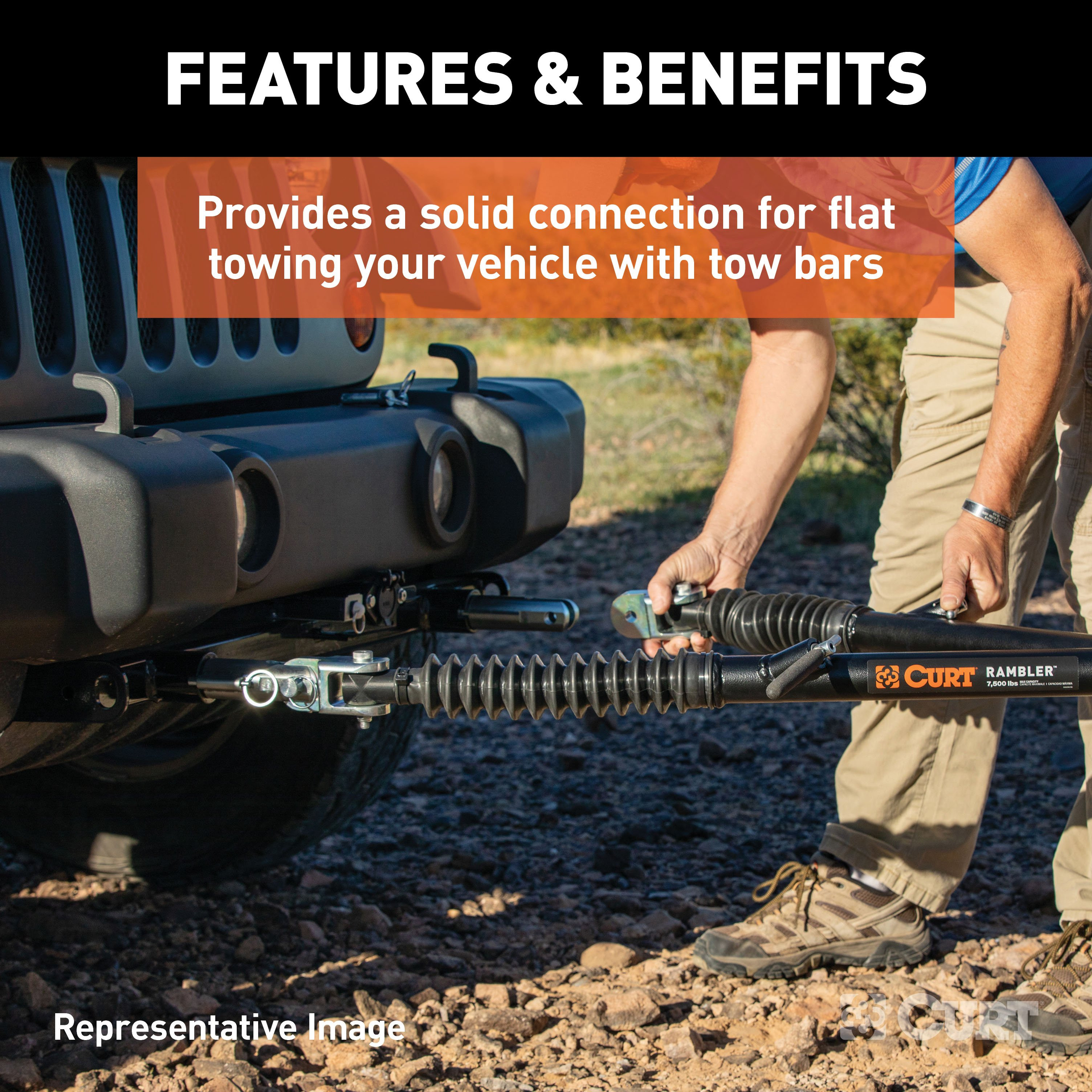
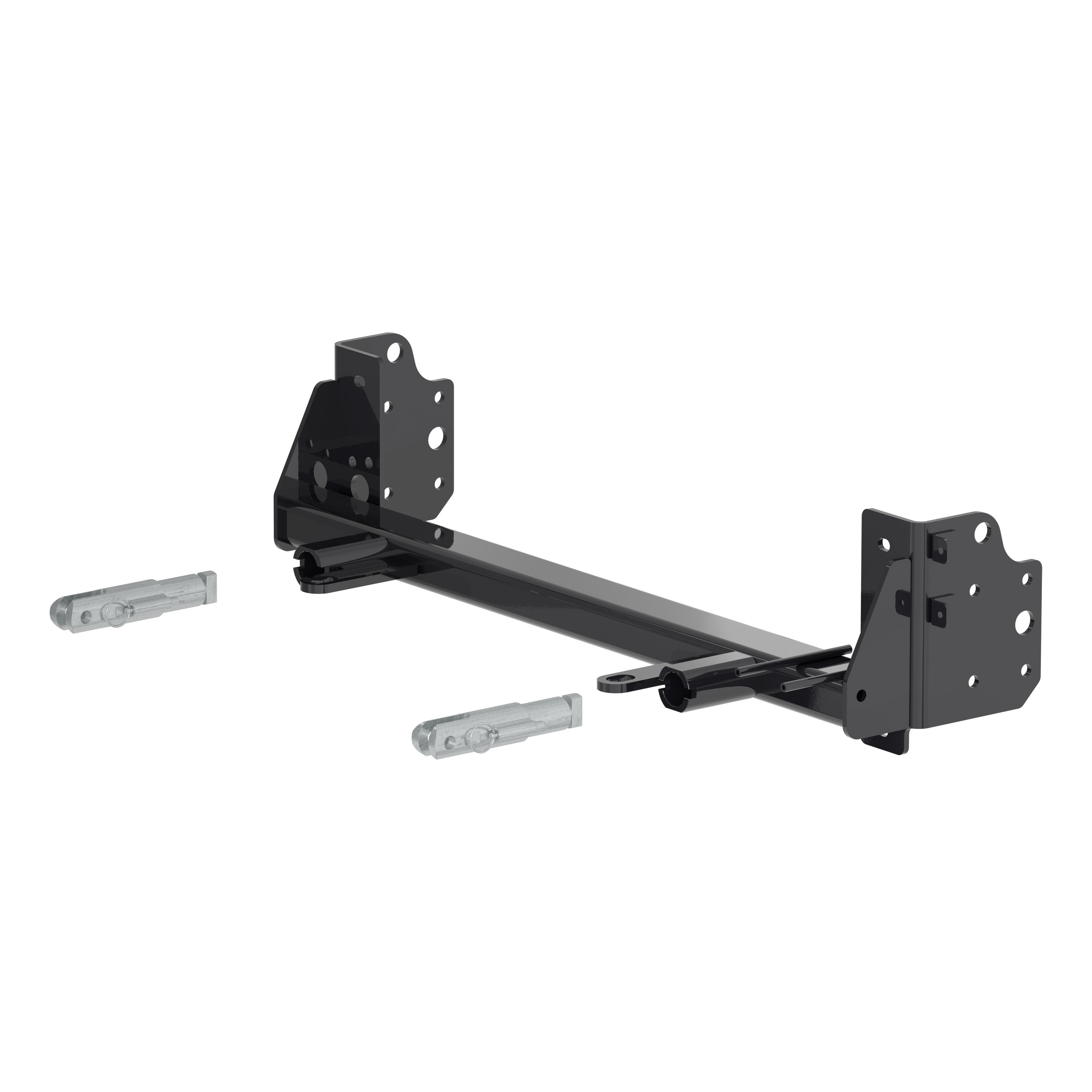
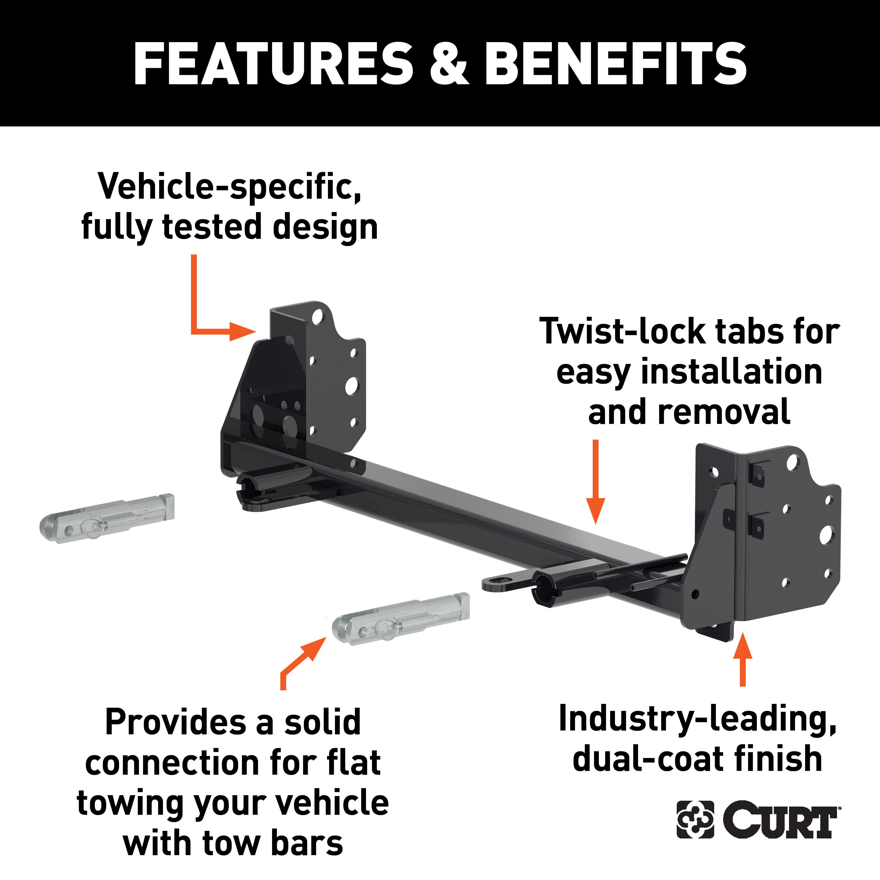
Provides a solid connection for dinghy towing your vehicle with tow bars
| Material | Carbon Steel |
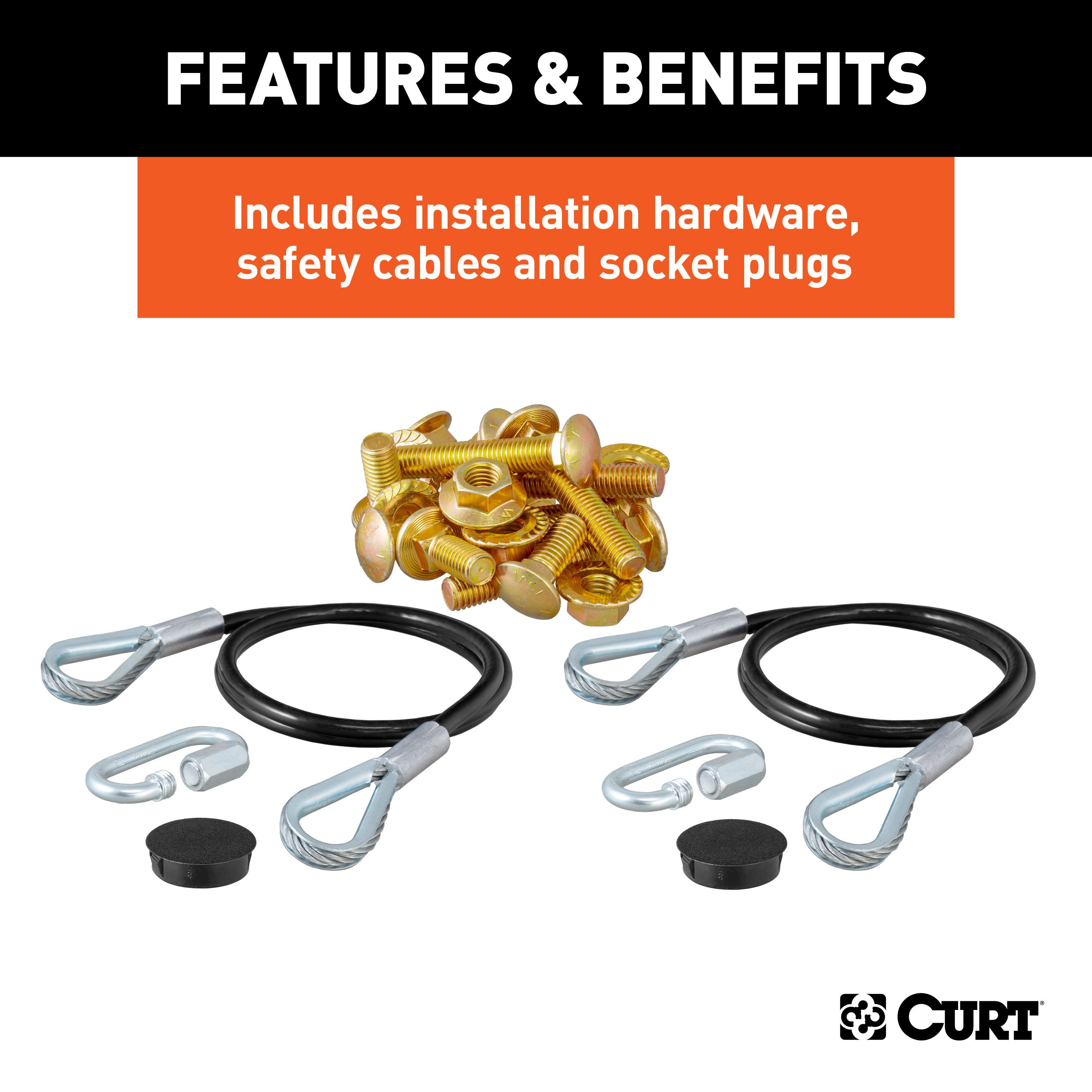
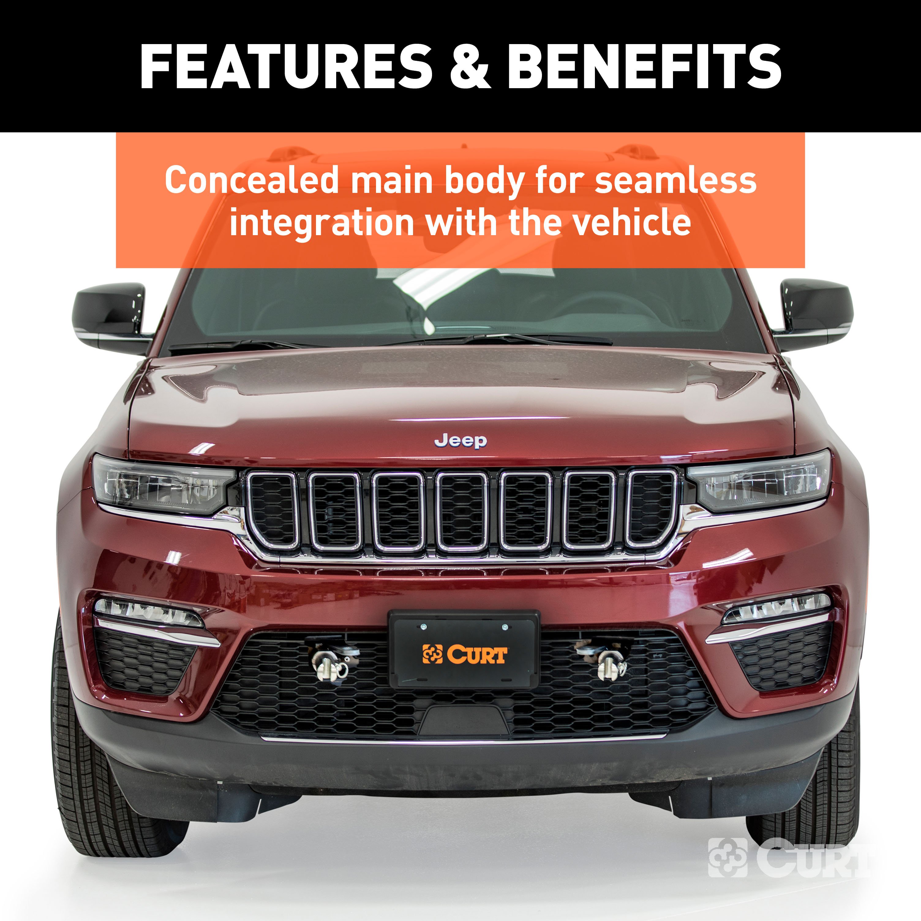
CURT tow bar base plates are engineered for a custom fit on each unique vehicle. This custom tow bar base plate fits select years of the Jeep Grand Cherokee (see application info to verify fitment). It features an OE style design to fully integrate with the front of the vehicle and maintain a factory look. This Jeep Grand Cherokee tow bar baseplate is constructed from high-quality steel and is precisely welded for a perfect fit. It is physically tested for absolute safety and peace of mind while dinghy towing. It also features a unique co-cured finish of liquid A-coat and highly durable powder coat to protect against the outdoor elements. This base plate for towing comes with attachment tabs, safety cables and installation hardware.

CURT offers a variety of high-quality trailer hitches and accessories for select vehicle models. Find the perfect fit for your towing needs at TowUniverse.
CURT, a Lippert brand, offers a complete line of towing products and is the leading manufacturer of custom-fit trailer hitches. We offer the broadest selection of custom-fit hitches, and each one is designed, welded, and coated in Wisconsin.
CURT is also a leader in flat towing products, as well as 5th wheel, gooseneck, and weight distribution hitches, ball mounts, electrical components, cargo solutions, and other towing accessories.
For everything from passenger cars and vans to full-size pickups and SUVs, CURT is 'The First Name in Towing Products®.'

Experts available to answer your questions
Call 888-634-9494Limited lifetime warranty (one-year finish, one-year parts)
Rediscover "Us" Time | Tested. Proven. Safe. Towing Products
1 compatible vehicles
| Year | Make & Model | Notes |
|---|---|---|
| 2022 - 2025 | Jeep Grand Cherokee | — |
The CURT 70153 Custom Tow Bar Base Plate Brackets for Dinghy Towing, Fits Select Jeep Grand Cherokee (Part #BKDK70153) fits 2022-2025 Jeep Grand Cherokee models. The 2025 model year is the last year covered by this part number. For newer models, check for an updated version.
The CURT 70153 Custom Tow Bar Base Plate Brackets for Dinghy Towing, Fits Select Jeep Grand Cherokee (Part #BKDK70153) fits the following vehicles: 2022-2025 Jeep Grand Cherokee. Always verify your specific year, make, and model before ordering.
Yes, the CURT 70153 Custom Tow Bar Base Plate Brackets for Dinghy Towing, Fits Select Jeep Grand Cherokee (Part #BKDK70153) is designed to fit the 2022-2025 Jeep Grand Cherokee.
The CURT 70153 Custom Tow Bar Base Plate Brackets for Dinghy Towing, Fits Select Jeep Grand Cherokee (Part #BKDK70153) Refer to the included instructions for installation details. Basic hand tools are typically all you need.
The manual does not specify a towing capacity for the 70153. The manual states that you must never exceed the vehicle manufacturer's recommended towing capacity. Refer to your vehicle's owner's manual for towing limits, and contact CURT Manufacturing at 877.287.8634 for the product's rated capacity.
Yes, on 2023 and newer Jeep Grand Cherokee models, removal and reinstallation of the front fascia during base plate installation may affect the vehicle's radar system, potentially causing malfunctions in the AEB (Automatic Emergency Braking) and ACC (Adaptive Cruise Control) systems. If these issues occur, take your vehicle to a certified Jeep dealership to have the system recalibrated.
Required tools are: flat screwdriver, Phillips screwdriver, reciprocating saw, hole saw (1-1/4"), drill, utility knife, drill bit (1/2"), torque wrench, ratchets (1/2" and 3/8"), Torx bit (T-40), sockets (3/4", 8mm, 10mm, 16mm, 17mm), Loctite RED, large vise grips, grinder, trim removal tools, and tape measure. The manual rates installation difficulty as Difficult.
The manual does not state whether professional installation is required or recommended. Installation is rated as Difficult and requires specialized tools including a reciprocating saw, hole saw, grinder, and torque wrench. Contact CURT Manufacturing at 877.287.8634 for guidance on whether to hire a professional installer.
Yes, drilling is required. Step 22 requires drilling a new 1-1/4" hole on each side of the frame, located 3" down from the center of the top bolt hole and centered horizontally. Step 25 also requires drilling four 1/2" holes on the side of the frame using the base plate as a template on each side.
Trimming is required in multiple locations: Step 18 requires trimming the frame using a reciprocating saw on both sides. Step 20 requires trimming the shroud on each side of the bottom shutters using a utility knife or reciprocating saw (do not cut the temperature sensor wire harness). Step 21 requires trimming the upper plastic shroud on both sides. Step 25 requires marking and trimming the fascia around the electrical mounting rods, convenience links, and attachment tabs as needed for fitment. The manual notes that additional trimming may be required beyond what is shown.
Yes, most modifications are permanent. The bumper is permanently removed (Step 14). Frame trimming (Step 18) and shroud trimming (Steps 20–21) are permanent cuts. The new 1-1/4" and 1/2" holes drilled in the frame (Steps 22, 25) are permanent. However, removal of the bumper fascia, skid shield, fenders, and wheel well are temporary—these components are reinstalled after base plate installation.
The removal sequence is: (1) Remove ten push pins and fascia cover (Step 1); (2) Remove six bolts from top of grille using T-40 Torx (Step 2); (3) Remove one bolt from top of grille using 10mm socket on both sides (Step 3); (4) Remove five bolts from wheel well edge using 8mm socket on both sides (Step 4); (5) Pull back wheel well liner and remove one bolt from fascia joint using 10mm socket on both sides (Step 5); (6) Remove five bolts from belly pan using 8mm socket (Step 6); (7) Remove one bolt from underside of fascia in front of tire using 8mm socket on both sides (Step 7); (8) Remove four bolts from belly pan using 10mm socket (Step 8); (9) Remove two bolts and two push pins from underside of fascia using 10mm socket (Step 9); (10) Unplug electrical connections and disconnect washer fluid lines on both sides (Steps 10–11); (11) Pull fenders outward (Step 12); (12) Release fascia clips and remove fascia (Step 13); (13) Remove bumper using 16mm socket and 10mm socket (Step 14); (14) Remove pedestrian alert system (Steps 15–16); (15) Remove horns (Step 17).
The fishwire technique is used to guide bolts and spacers through the vehicle frame rail without losing them inside the frame. The coiled end of the fishwire tool is inserted through the hitch mounting hole in the vehicle frame rail and out the access hole. The coiled end is passed through the spacer, and the bolt is threaded into the coil. The wire is kinked to keep the spacer separate from the bolt. The fishwire is then pulled to draw the spacer and bolt through the frame and out the mounting hole. This technique is used in Steps 26, 27, and 28 to install the 1/2" x 1-1/2" carriage bolts with spacers.
Yes, Loctite RED is required. It must be applied to the existing bolts (#2) in Step 24 and to all 1/2" x 1-1/2" carriage bolts (#7) in Steps 26, 27, and 28. Once Loctite RED has been applied, the hardware must be tightened to the specified torque within 10 minutes, unless otherwise directed on the Loctite container.
Two torque specifications are provided: (1) The existing bolts (#2) in the top and bottom holes are torqued to 45 ft-lb with Loctite RED (Step 24). (2) All eight 1/2" x 1-1/2" carriage bolts (four on each side) are torqued to 110 ft-lb (Step 28). Loctite RED must be applied and bolts must be tightened within 10 minutes.
The existing bolts (#2) in the top and bottom holes should be torqued to 45 ft-lb with Loctite RED applied. The bolts must be tightened within 10 minutes of applying Loctite RED.
All eight 1/2" x 1-1/2" carriage bolts (four on each side) should be torqued to 110 ft-lb with Loctite RED applied. The bolts must be tightened within 10 minutes of applying Loctite RED.
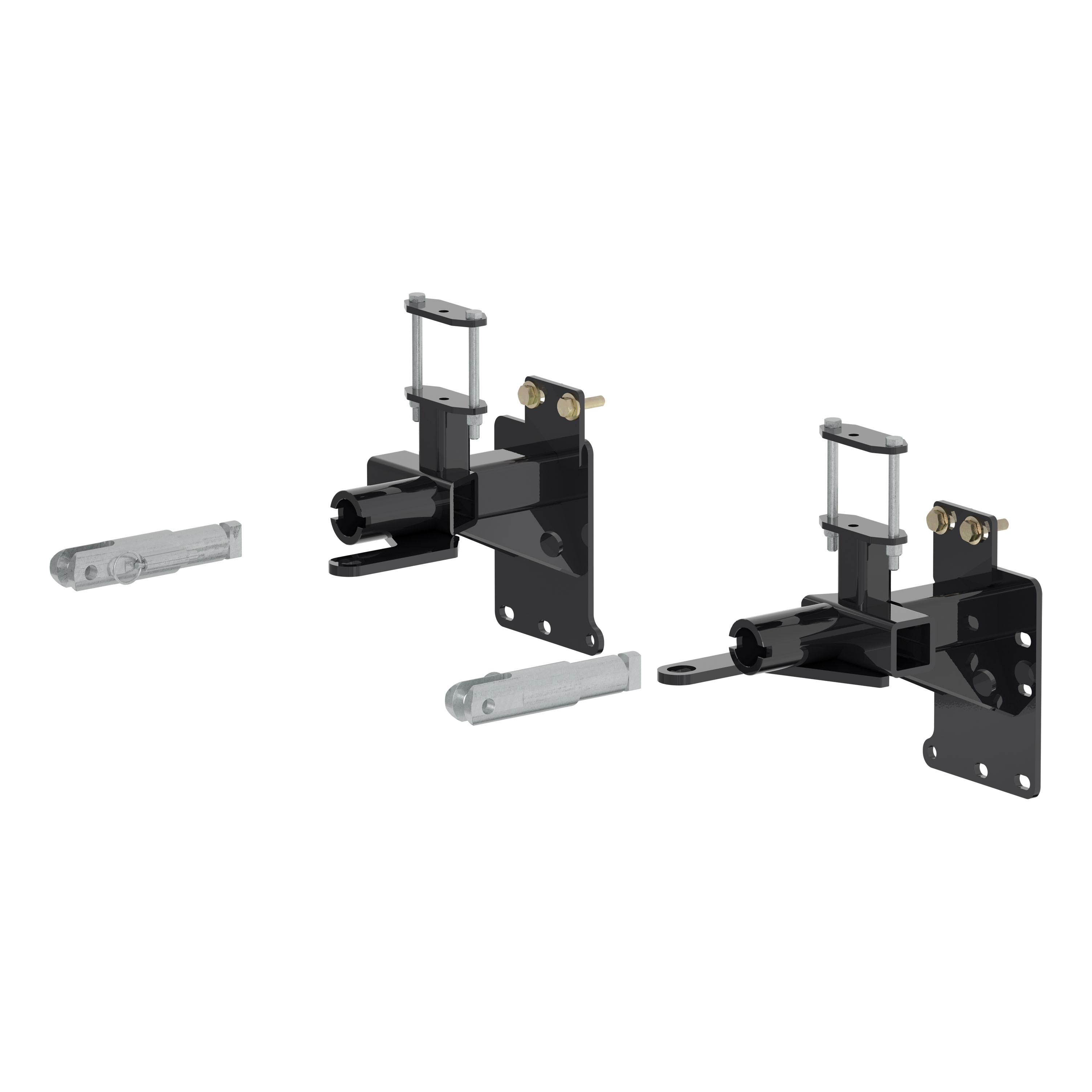
The parts list includes: (1) 2 Flange Bolts M6 x 1 (existing, top and bottom holes); (2) 4 HHCS M10 x 1.5 (existing); (3) 1 Base Plate; (4) 2 Side Plate Spacers (inserted at top of base plate between frame and base plate, slotted end facing downward, Step 27); (5) 1 Electrical Flat Bracket; (6) 2 Base Plate T-Bolt Pin Assemblies Long; (7) 8 Bolts CAR 1/2-13 UNC 1-1/2 Grade 8 YZ (carriage bolts for frame mounting); (8) 8 Square hole spacers 0.250 x 1.00 x 2.00" (installed with carriage bolts); (9) 8 Nuts SER-FLANGE 1/2-13 UNC Grade 8 YZ (serrated nuts for carriage bolts); (10) 2 SDSHW 12-14 1 ZP; (11) 2 Caplugs DOP-1375; (12) 2 Quick links 0.500" (for safety cable attachment); (13) 8 Fishwires 1/2" (for guiding bolts through frame); (14) 2 Safety Cables 7500 lb (attached to base plate and vehicle frame).
In Step 26, the 1/2" x 1-1/2" carriage bolts with spacers and serrated nuts in the bottom front holes are started but left loose at this time. All bolts are then torqued to their final specifications in Step 28 after the spacer plates are installed in Step 27.
In Step 27, insert the spacer plate (#4) at the top of the base plate between the frame and base plate with the slotted end facing downward. Once the spacer plate is in position, use the provided fishwire to insert the 1/2" x 1-1/2" carriage bolt (#7) with spacer (#8) and Loctite RED into the top front hole and start a 1/2" serrated nut (#9). Perform this process on both sides of the vehicle.
Two sets of holes are drilled: (1) In Step 22, create a mark on the frame 3" down from the center of the top bolt hole and centered horizontally from the center of the top bolt hole. Using a 1-1/4" hole saw, drill a new hole. Perform this on both sides of the vehicle as needed. (2) In Step 25, using a 1/2" drill bit, drill four holes on the side of the frame using the base plate as a template. Perform this on both sides of the vehicle.
In Step 24, hold the base plate into place on the vehicle frame and start the existing bolts (#2) in the top and bottom holes on both sides of the vehicle. Ensure all holes line up before tightening bolts. Then use Loctite RED and torque to 45 ft-lb.
In Step 10, unplug one electrical connection on the passenger side of the vehicle. If present, disconnect washer fluid lines going to the front of the fascia. In Step 11, unplug one electrical connection on the driver side of the vehicle. If present, disconnect washer fluid lines going to the front of the fascia. The number of plugs and lines to disconnect varies depending on the trim level of the vehicle. In Step 15, unplug the pedestrian alarm. In Step 19, remove the plastic push pin holding the temperature sensor and feed it through the plastic on the passenger side (do not unplug the temperature sensor).
No. In Step 19, the manual explicitly states: "Do not unplug the temperature sensor." Only remove the plastic push pin holding the temperature sensor and feed it through the plastic on the passenger side of the vehicle. Move the sensor to a secure location out of the way for the duration of the base plate installation, and reinstall it later in Step 30.
No. In Step 20, the manual explicitly states: "Do NOT cut the temperature sensor wire harness." When trimming the shroud on each side of the bottom shutters, take care to avoid the temperature sensor wire.
In Step 25 (the final step), hold the fascia as close to its original position as possible. Mark and trim the fascia around the electrical mounting rods, convenience links, attachment tabs, and electrical mounting rods as needed for fitment. Then reinstall the fascia, fascia cover, wheel well liner, fender trim, and belly pan. Make sure all electrical connectors are reconnected properly and any other connectors or lines depending on vehicle trim are reconnected.
After the base plate is mounted, the following components are reinstalled: (1) In Step 30, reinstall the temperature sensor on the passenger side and reinstall the horns on both sides. (2) In Step 31, install clips from the pedestrian alert bracket onto the tabs on the passenger side of the base plate. (3) In Step 32, reinstall the pedestrian alarm on the passenger side of the base plate using the existing hardware. (4) In Step 25, reinstall the fascia, fascia cover, wheel well liner, fender trim, and belly pan, ensuring all electrical connectors are reconnected.
Safety glasses should be worn at all times while installing this product. The installation involves using power tools including a reciprocating saw, drill, hole saw, and grinder, as well as working under the vehicle. Never exceed the vehicle manufacturer's recommended towing capacity when using the hitch.
Two 7500 lb safety cables are included with the base plate. When dinghy towing a vehicle with a tow bar, base plate safety cables should be used at all times. In the event of a disconnect, the safety cables are designed to help prevent complete vehicle separation. Installation guidelines: (1) Cables must be connected to the base plate and the vehicle frame. (2) Two cables must be installed. (3) Each cable must meet or exceed the gross weight of the towed vehicle. (4) Make sure cables do not pinch or interfere with hoses, wiring, or other components. Note: Base plate safety cables are not a replacement for safety chains connecting the tow vehicle to the towed vehicle.
In Step 29, attach the permanent base plate safety cables (#14) to the provided hole with the provided 0.500" Quick Link (#12) on the base plate. Install the cables to the frame of the vehicle. Additional options may interfere with the suggested mounting locations. For this mounting, make sure the cable is secured around a solid piece of frame and is not rubbing on any hoses, wires, or moving parts.
After installation, periodic inspection of the trailer hitch should be performed to ensure all mounting hardware remains tight and structural components are secure. Check your equipment periodically to ensure all fasteners are tight and that all structural components are sound. Do not tow with worn or damaged parts. Ensure all electrical connectors are reconnected properly and any other connectors or lines depending on vehicle trim are reconnected.
The manual states that periodic inspection of the trailer hitch should be performed to ensure all mounting hardware remains tight and structural components are secure. The manual does not specify the exact interval for inspection. Check your equipment periodically and do not tow with worn or damaged parts.
The installed attachment tabs have a height of 22" and a width of 24".
Removal and reinstallation of the front fascia during base plate installation may affect the vehicle's radar system, potentially causing malfunctions in the AEB (Automatic Emergency Braking) and ACC (Adaptive Cruise Control) systems on 2023 and newer Jeep Grand Cherokee models. If these issues occur, take your vehicle to a certified Jeep dealership to have the system recalibrated.
In Step 25, the manual notes that additional trimming may be required beyond what is shown. Hold the fascia as close to its original position as possible and mark and trim the fascia around the electrical mounting rods, convenience links, attachment tabs, and electrical mounting rods as needed for fitment. If trimming does not resolve the fit issue, contact CURT Manufacturing at 877.287.8634 for support.
The fishwire technique is specifically designed to prevent loss of bolts or spacers inside the frame rail. The coiled end of the fishwire is passed through the spacer, and the bolt is threaded into the coil. The wire is kinked to keep the spacer separate from the bolt. The fishwire is then pulled to draw the spacer and bolt through the frame and out the mounting hole. If a bolt or spacer is lost, use the fishwire technique as described in Steps 26-28 to retrieve it, or contact CURT Manufacturing at 877.287.8634 for assistance.
Periodic inspection of the trailer hitch should be performed to ensure all mounting hardware remains tight and structural components are secure. If bolts have loosened, retorque them to the specified values: existing bolts (#2) to 45 ft-lb and carriage bolts (#7) to 110 ft-lb. Apply Loctite RED before retorquing and ensure bolts are tightened within 10 minutes of applying Loctite RED.
The installed attachment tabs have a height of 22" and a width of 24".
Yes, two 7500 lb safety cables are included. They must be installed and used at all times when dinghy towing. Safety cables are not a replacement for safety chains connecting the tow vehicle to the towed vehicle.
Two sizes of holes are drilled: a 1-1/4" hole on each side of the frame (Step 22) and four 1/2" holes on the side of the frame on each side (Step 25).
Installation is rated as Difficult. The installation requires removal of multiple components, trimming, drilling, and use of specialized tools including a reciprocating saw, hole saw, grinder, and torque wrench.
Yes, the bumper is permanently removed in Step 14 and will not be reinstalled. Other components such as the bumper fascia, skid shield, fenders, and wheel well are temporarily removed and reinstalled after base plate installation.
Free Shipping
Ships free on all orders
 Authorized Dealer



Quick Ship
In stock and ready to ship — order now!
Shipping from Lancaster, TXFREE SHIPPING
Estimated delivery Wed, Sep 23 - Fri, Sep 25
Order before 2 PM EST Monday–Friday for same-day processing
Guaranteed safe & secure checkout
No reviews have been added for this product.