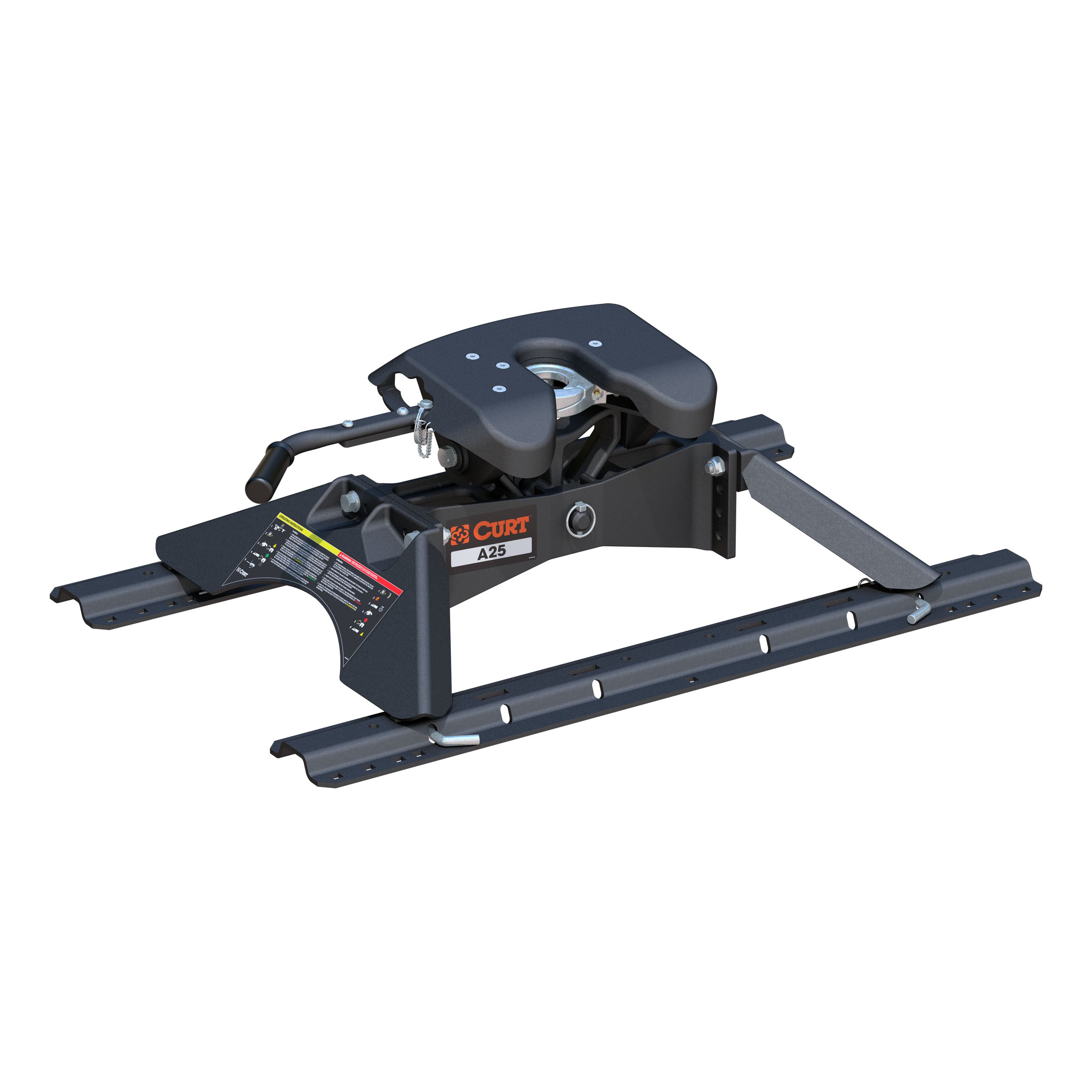
CURT 25K, A25 5th Wheel Hitch with RailsCURTOriginal price was $1,503.95. Current price is $1,241.95.In Stock
View productOur in-house experts typically reply within one business day.

CURT



Always the correct part
We know our products
Quality Products
Free Shipping!
Always the correct part
We know our products
Quality Products
Free Shipping!
On Sale Today
Original price was $1,249.95. Current price is $1,063.95.You save $186.00 (15%)
Free Shipping
Ships free on all orders
 Authorized Dealer


Quick Ship
In stock and ready to ship — order now!
Shipping from Eau Claire, WIFREE SHIPPING
Estimated delivery Fri, Sep 18 - Sun, Sep 20
Order before 2 PM EST Monday–Friday for same-day processing
Guaranteed safe & secure checkout
Includes 5th wheel head, legs and hardware (patent# 8,827,298)
Each truck-trailer configuration is different. Be sure to review each configuration and always ensure adequate trailer-to-cab clearance when maneuvering.
Capacity limited to lowest-rated towing component

Includes 5th wheel head, legs and hardware (patent# 8,827,298)
Warranty: Limited Lifetime Warranty (One-Year Finish, One-Year Parts)
Color: Black
Finish: CARBIDE BLACK POWDER COAT
Gross Trailer Weight (Pounds): 25,000 LB
Installation Time Exact (Minutes): 0
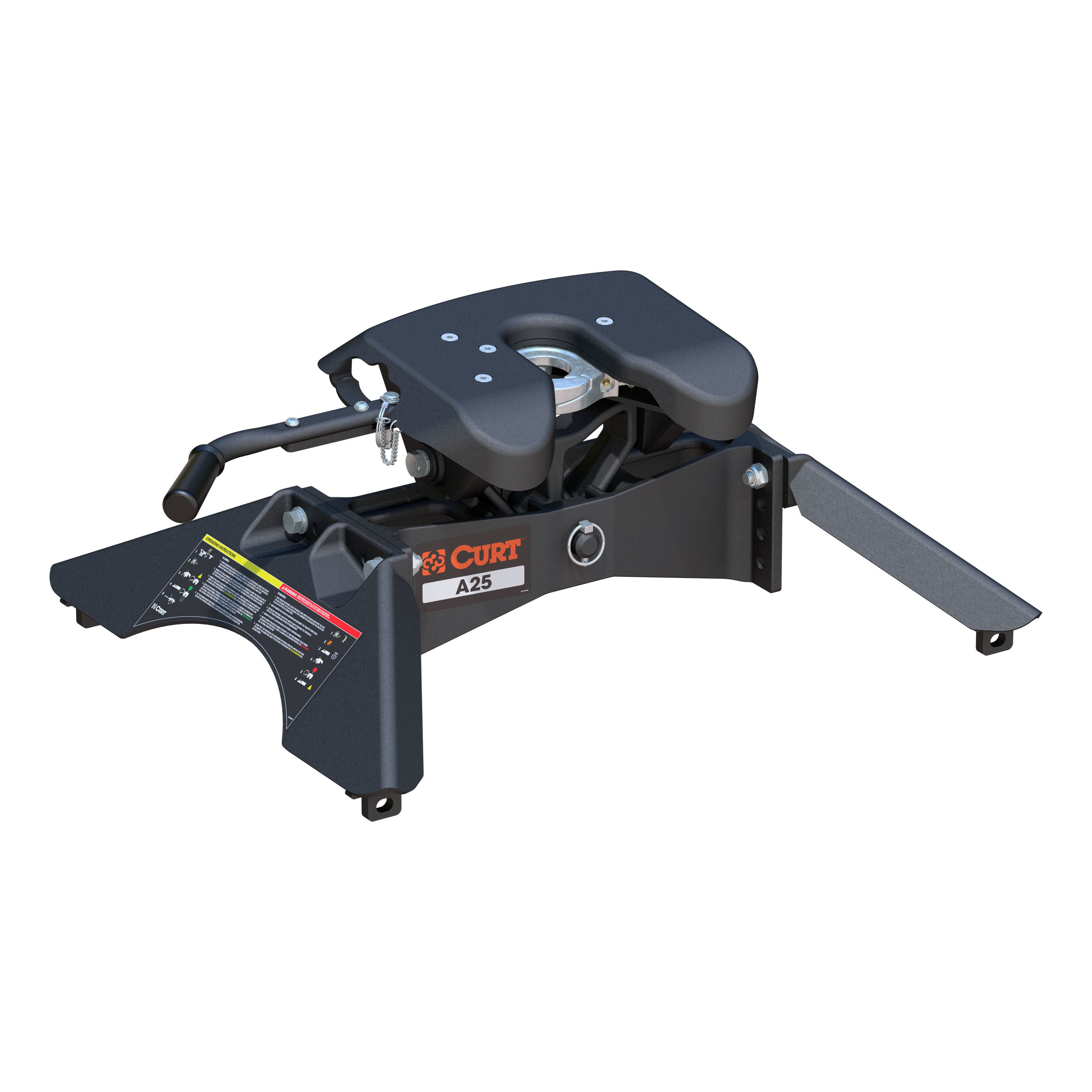
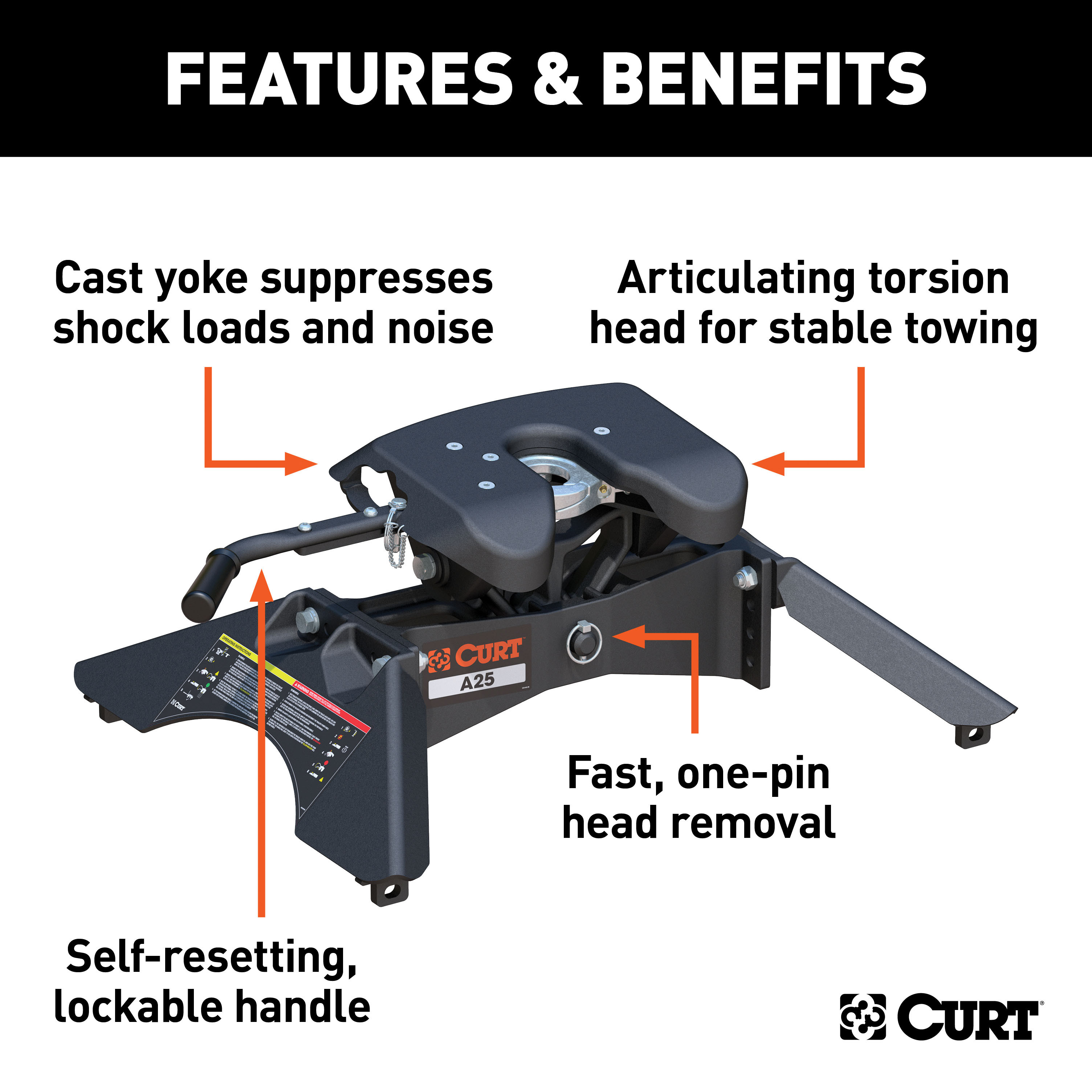
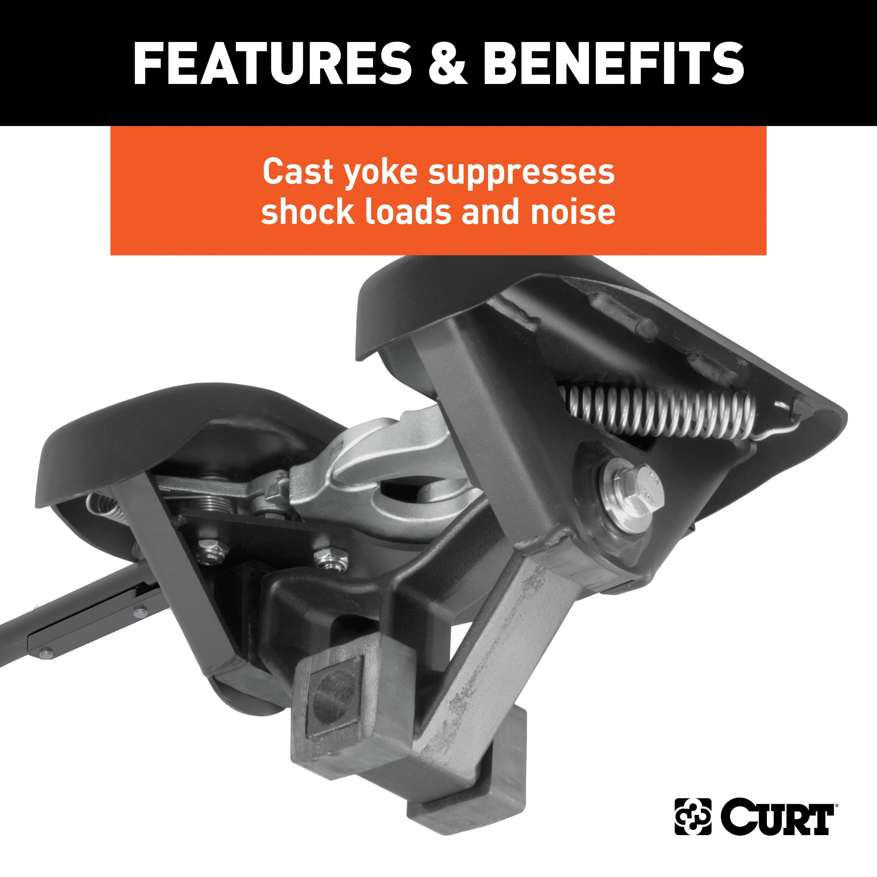
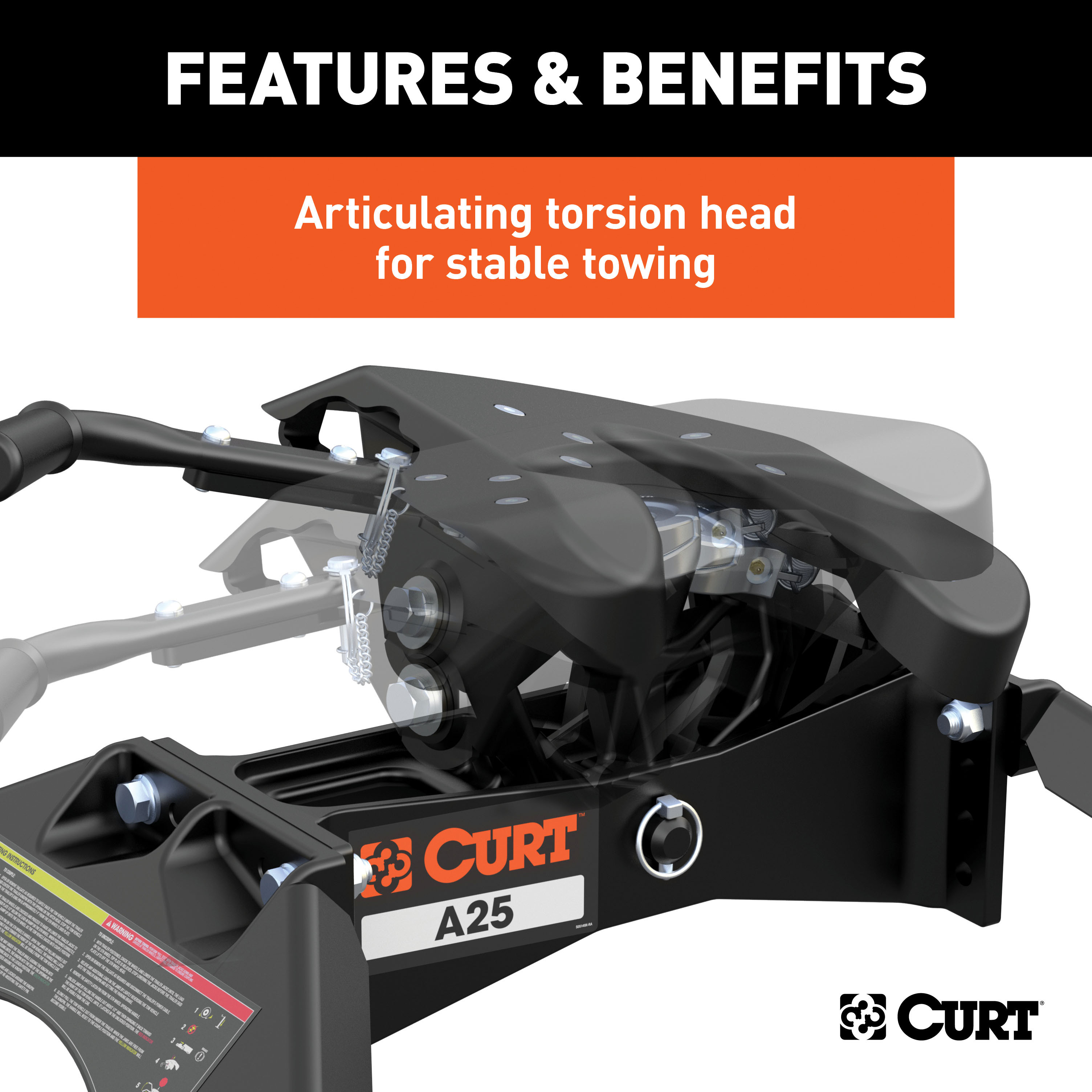
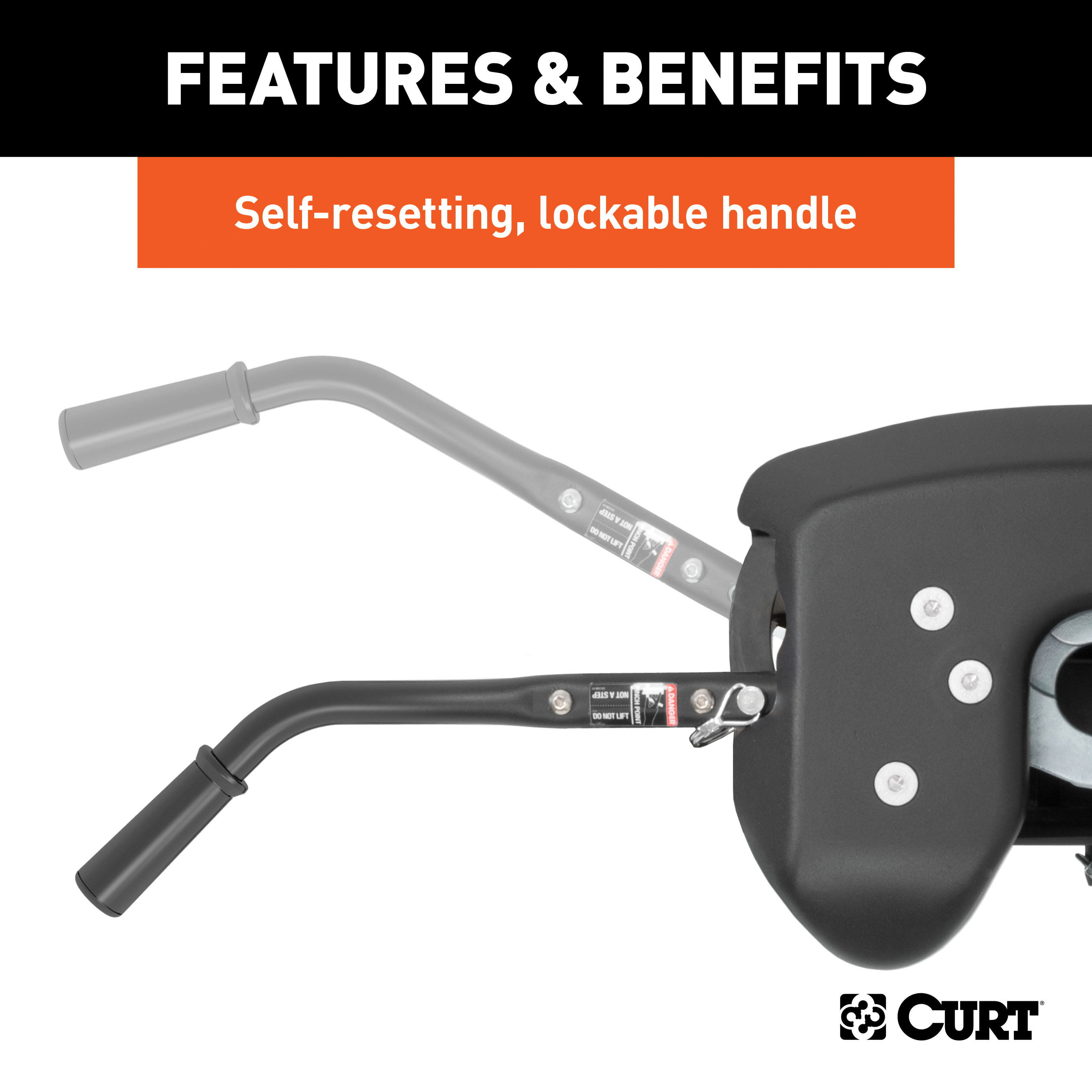
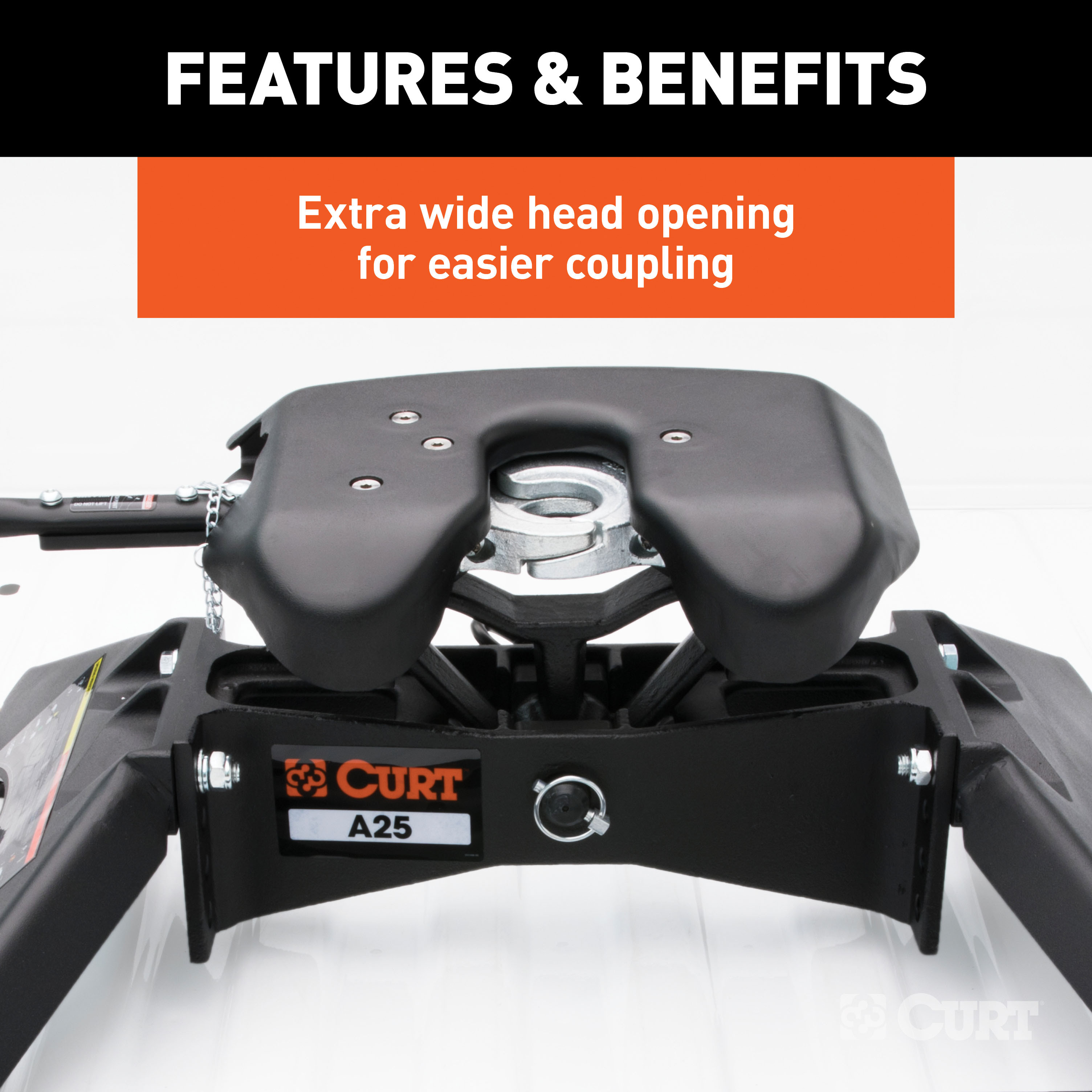
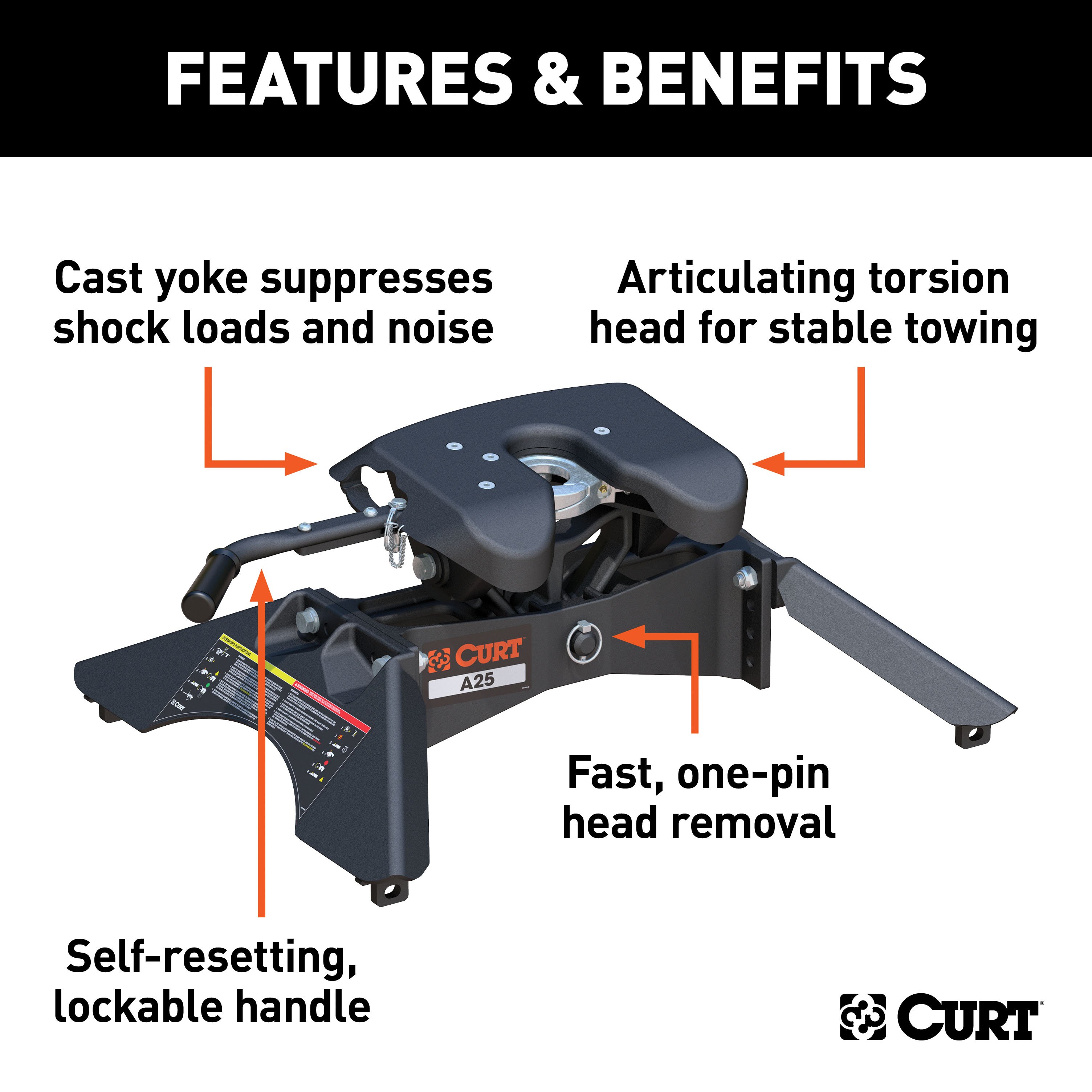
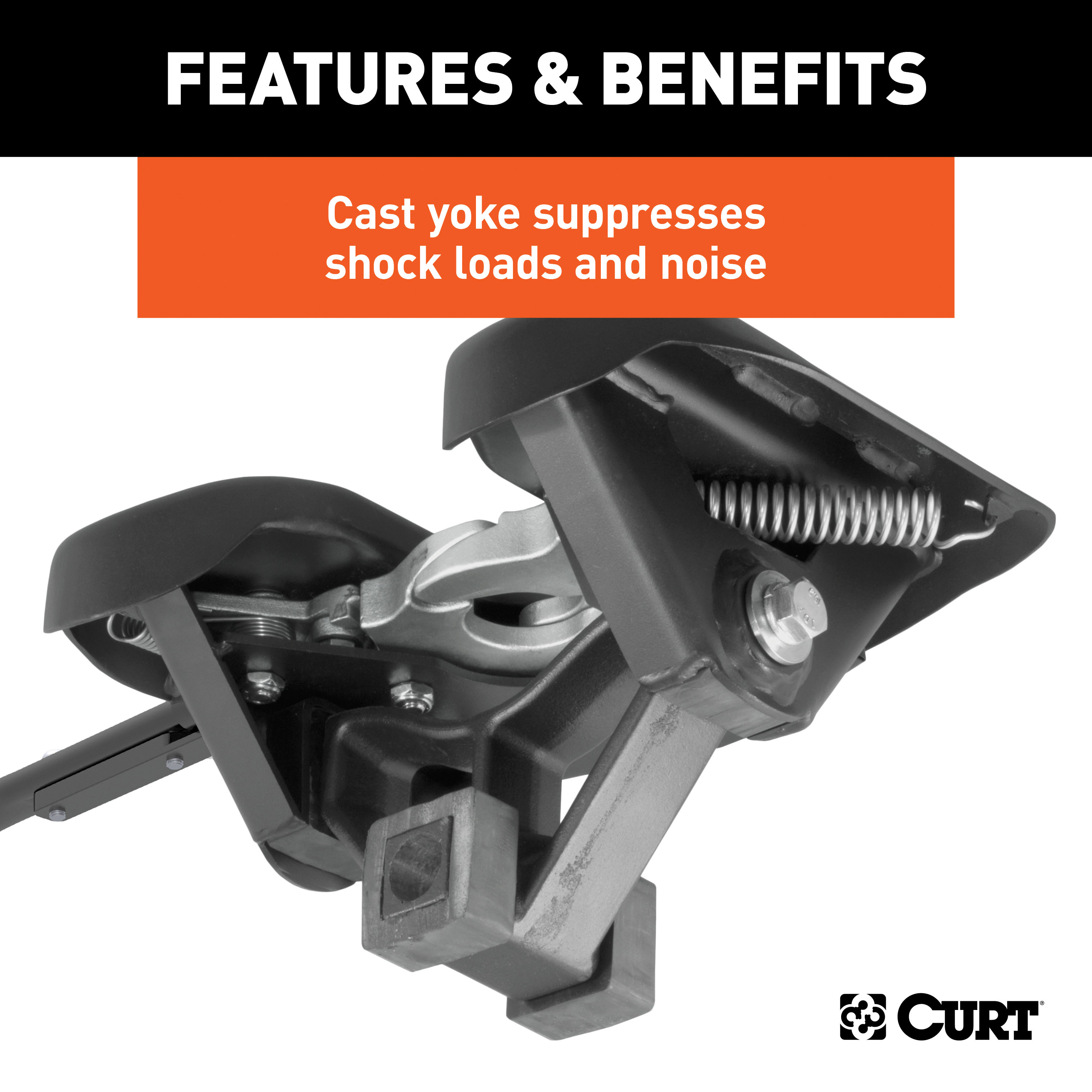
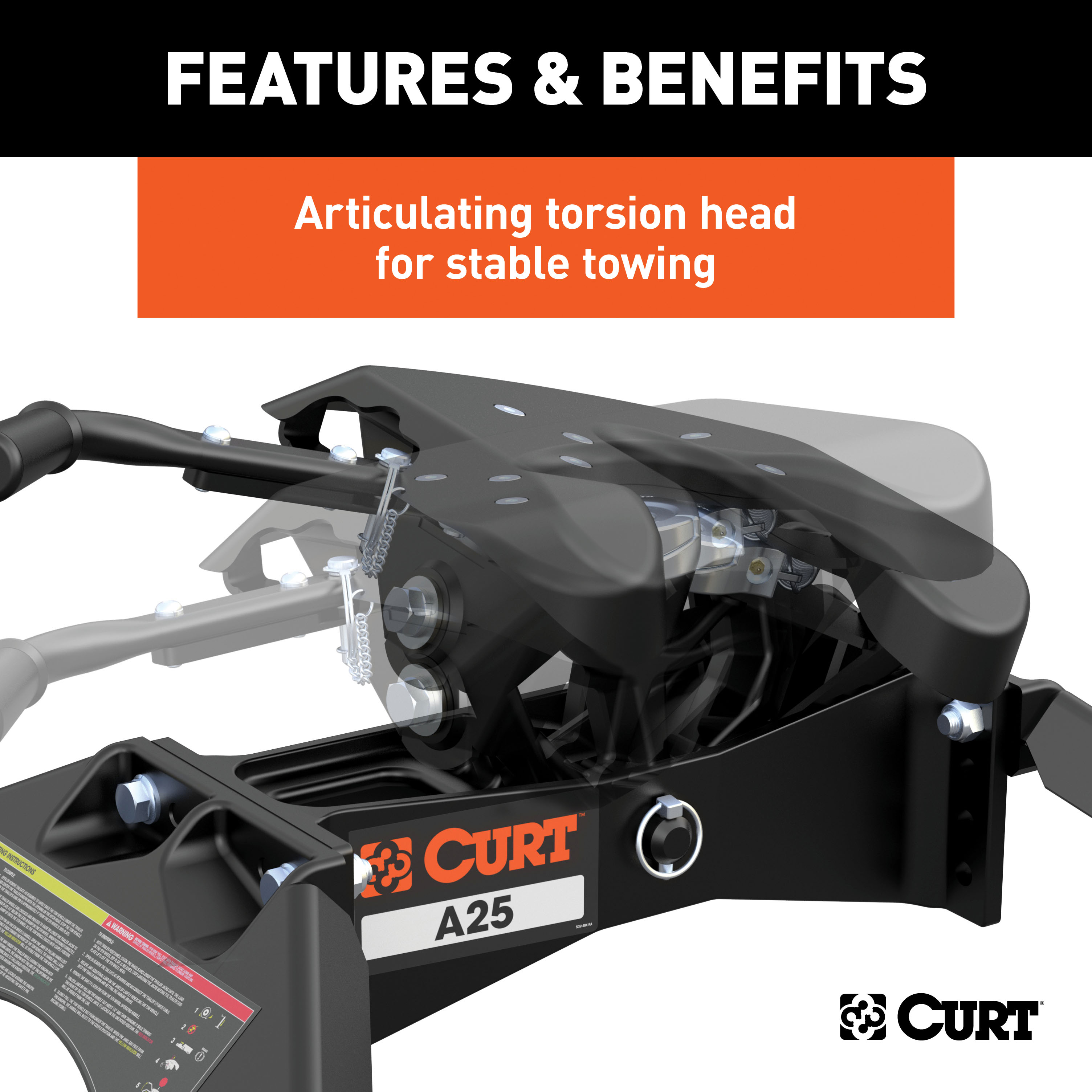
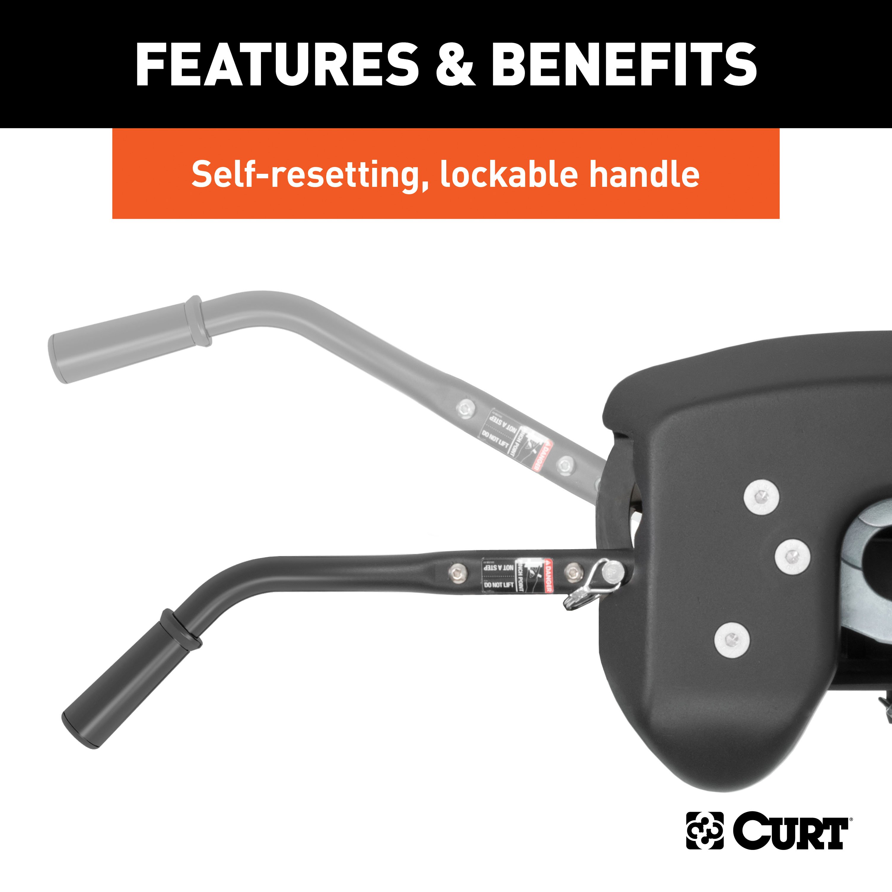
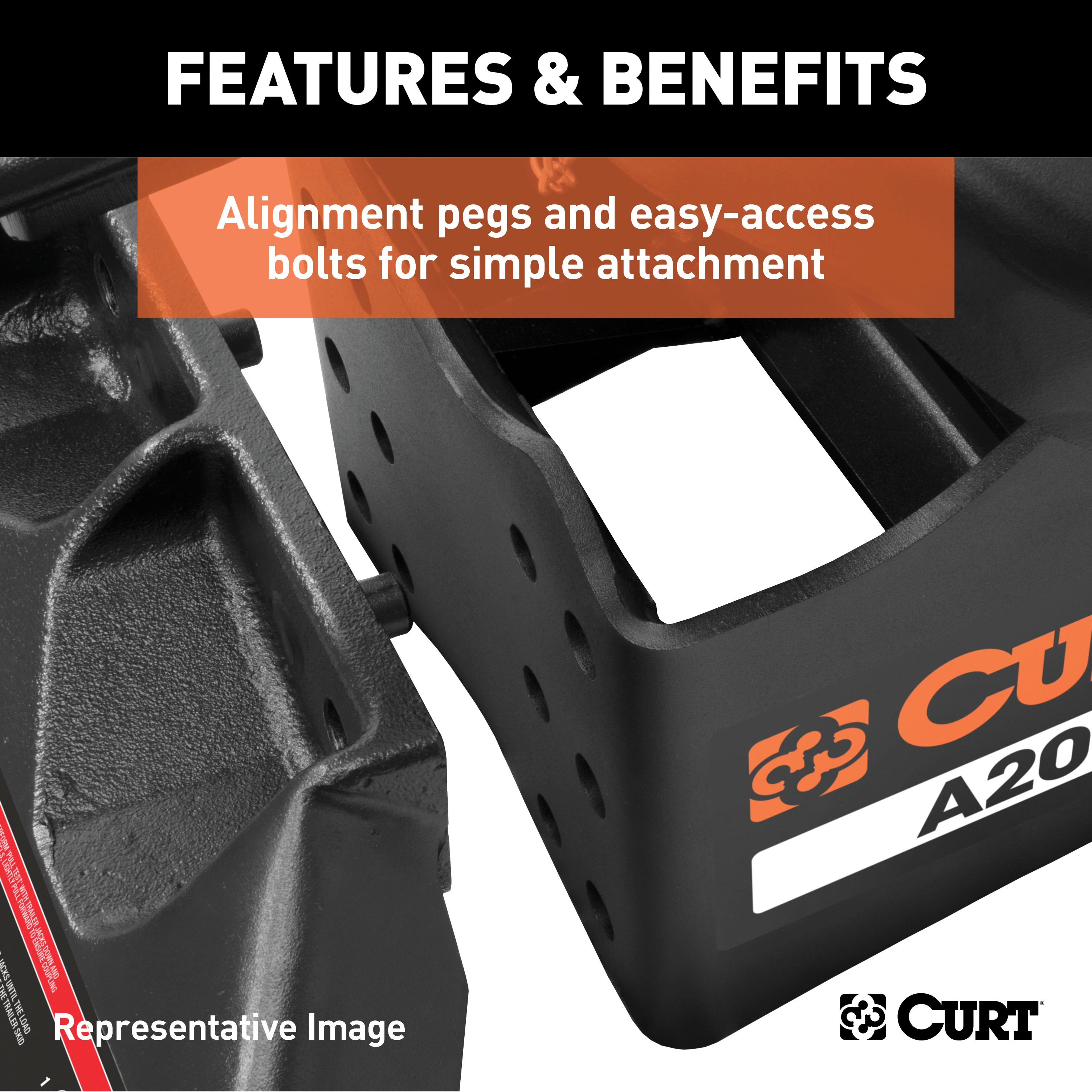
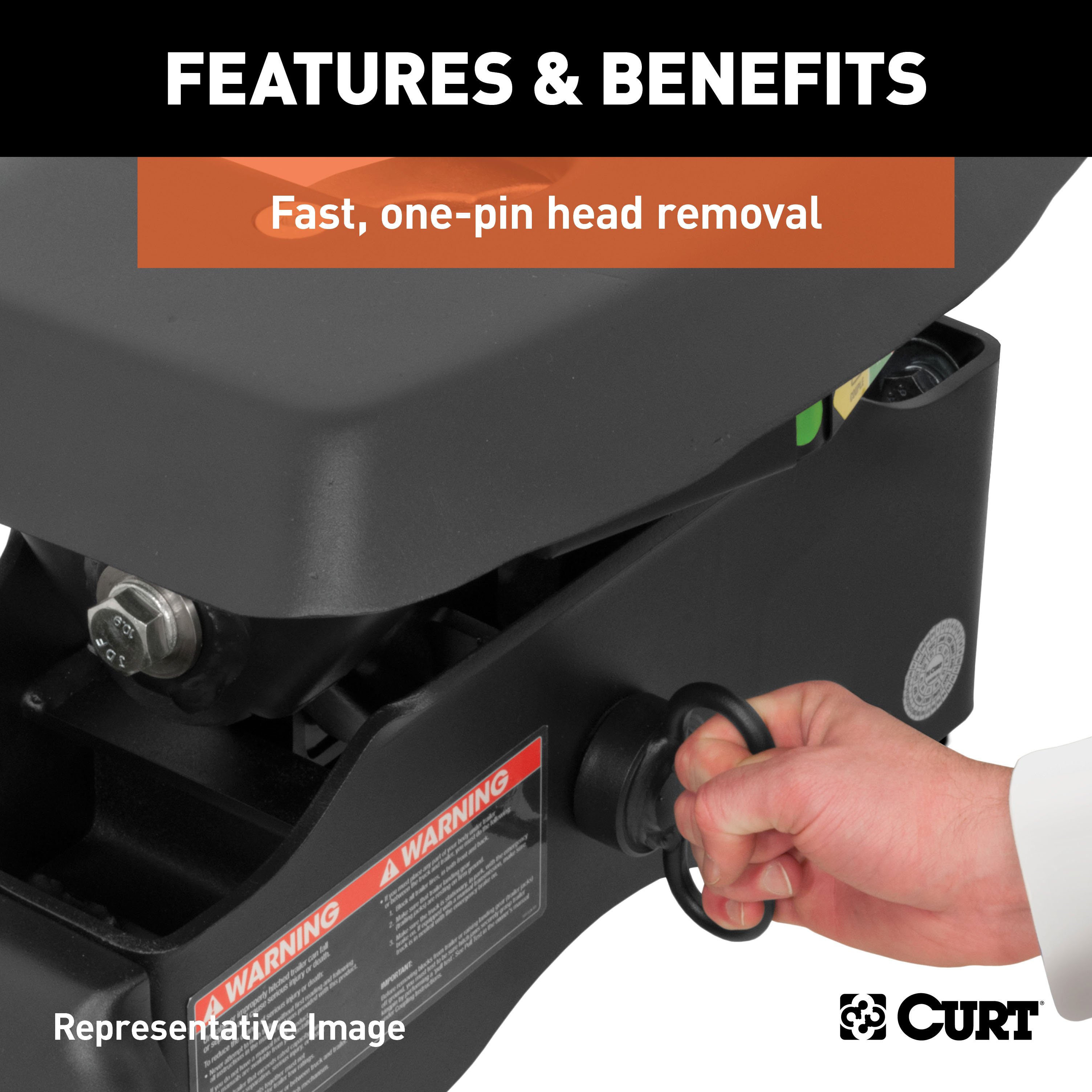
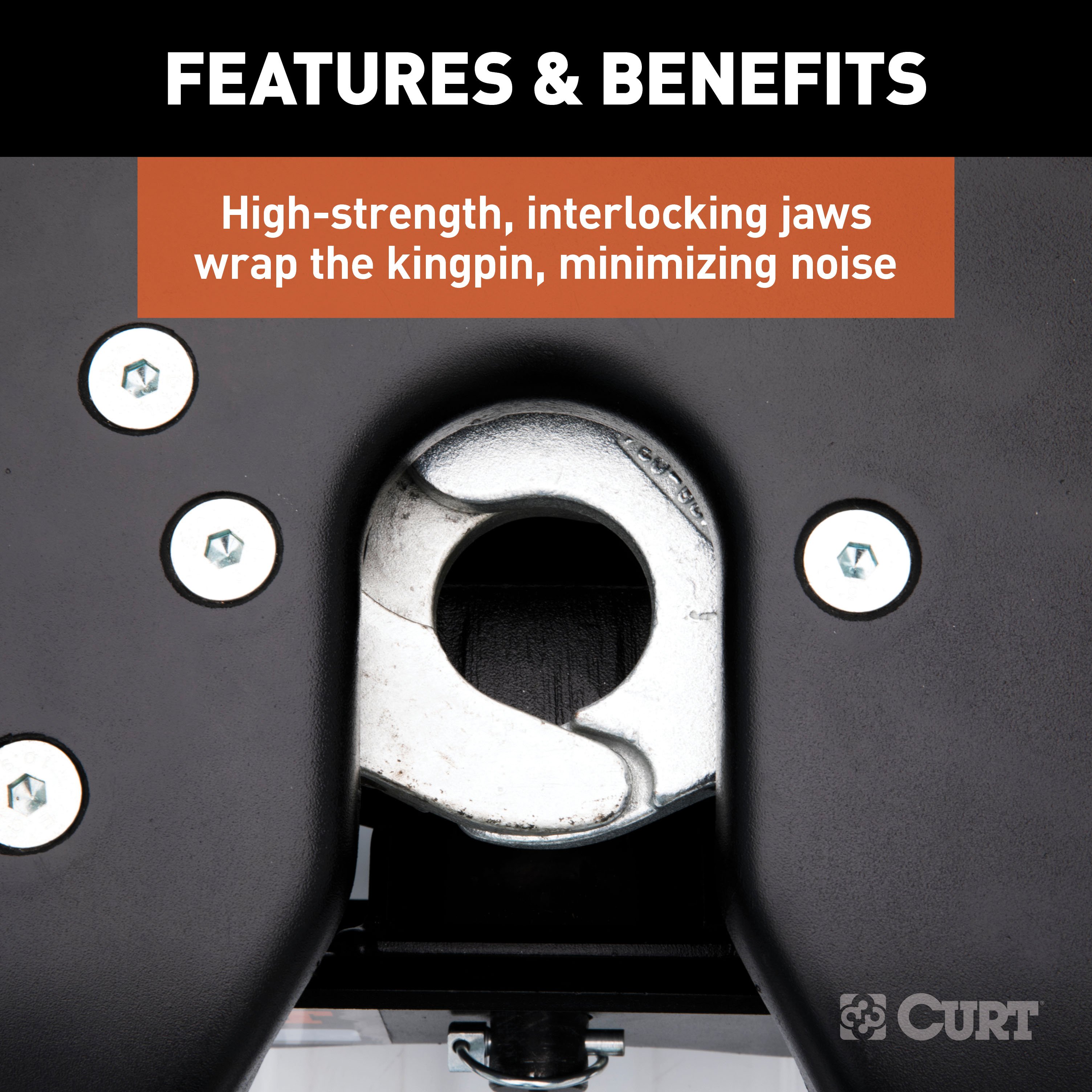
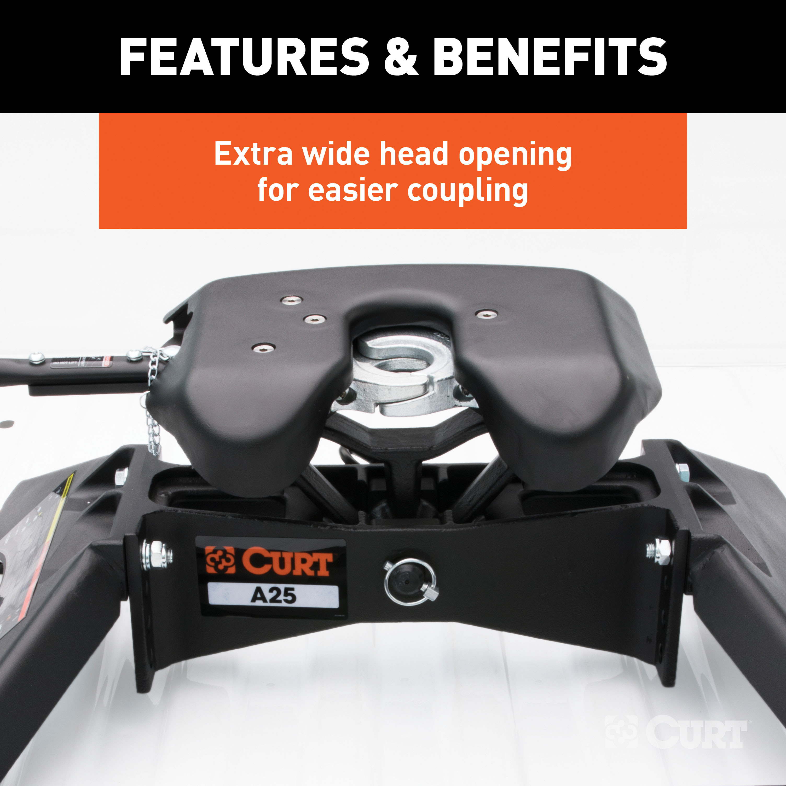
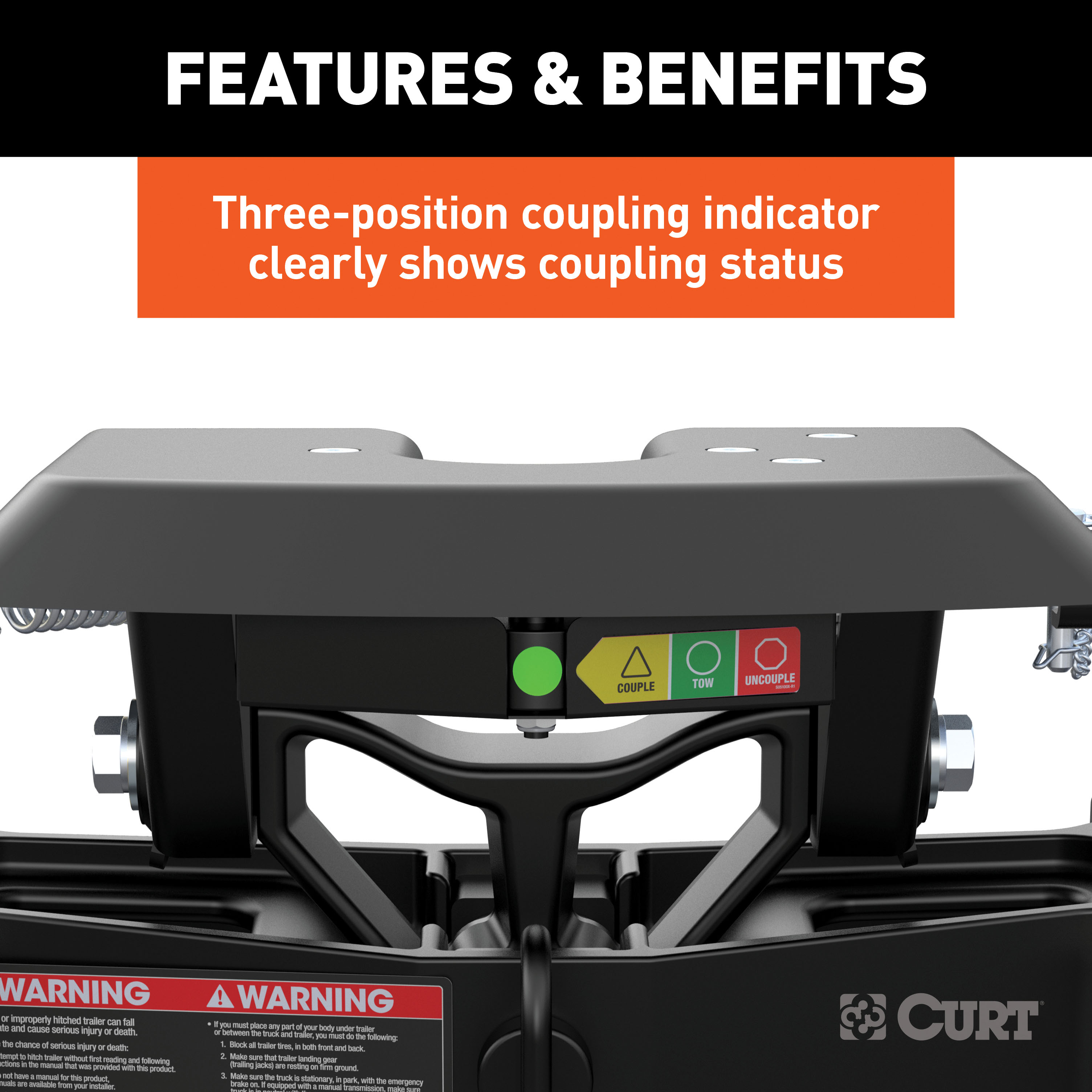
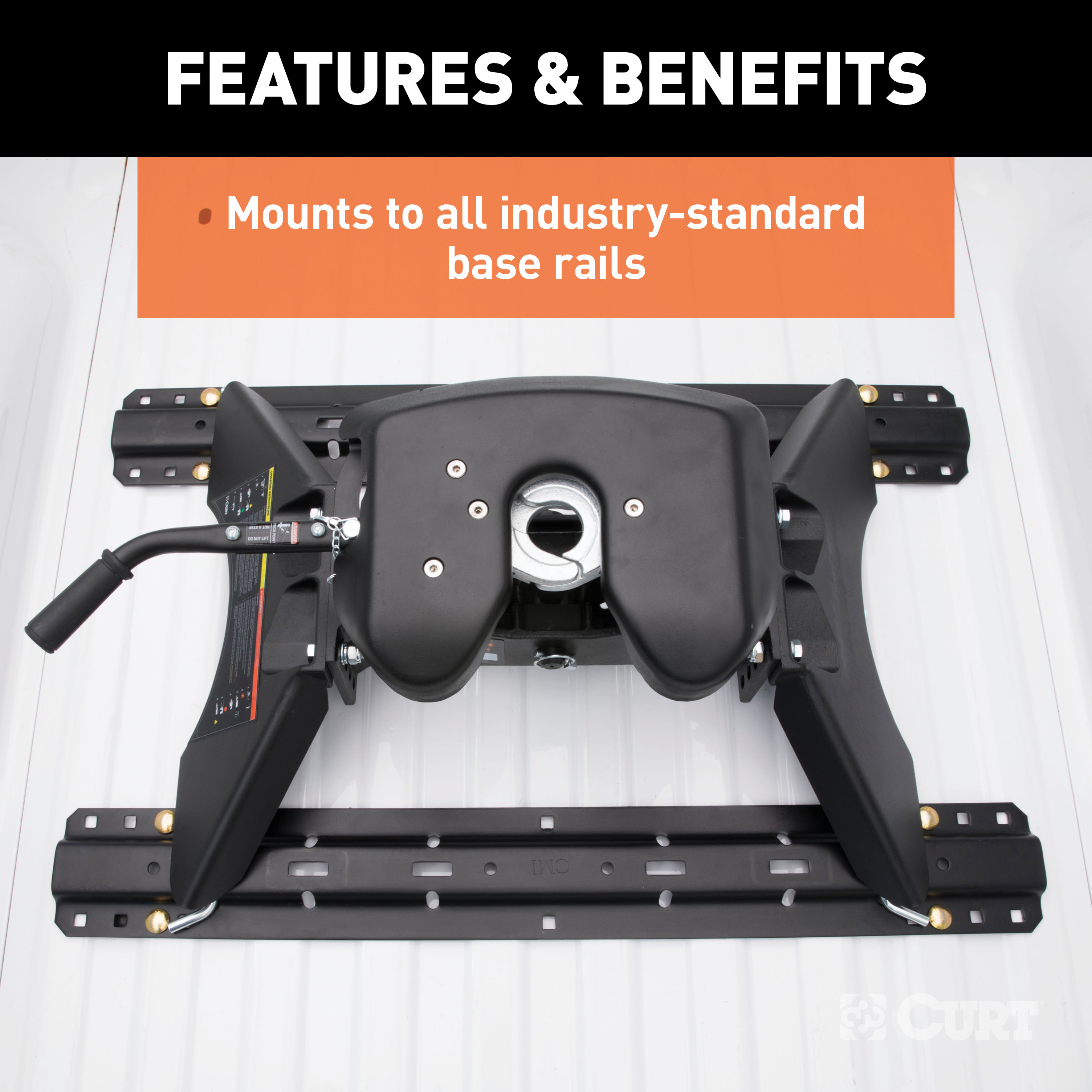
The CURT A25 5th wheel hitch offers smoother, quieter towing for your home-away-from-home, combining the patented technology of our A-series, an easier mounting system and the power of a 25K 5th wheel hitch. Like our A16 and A20 hitches, this 25K 5th wheel hitch uses a patented cast yoke to allow for unimpeded head movement, while providing exceptional stability for the trailer. The yoke has a set of poly-torsion inserts to suppress shock loads and reduce excessive noise, and the head features high-strength, interlocking jaws to give the trailer stability and the freedom to pivot and swivel as needed. The A25 5th wheel hitch is also engineered for easier installation. The legs are equipped with two pins to properly align with the mounting holes, and they have easy-access mounting bolts for ergonomic tightening. The 5th wheel head also has a fast, one-pin removal system to make installation and removal from the truck bed easier. This 25K 5th wheel mounts to any industry-standard 5th wheel rails, using the 5th wheel legs or a CURT 5th wheel roller. It can also be mounted into the puck system of a truck equipped with the towing prep package, using our OEM puck system legs or roller adapters. Once installed, the A25 is fast and simple to operate. It features an extra-wide head opening to increase the coupling area for the trailer, and it has a lockable, single-throw handle that self-resets to the ready-to-couple position after uncoupling. To make coupling even easier, it is equipped with a coupling indicator that is visible from the truck cab. The indicator shows the status of the connection and eliminates the need for you to check multiple times while coupling. To protect the A25 5th wheel hitch against rust, wear and whatever other threats might impede your cross-country tour, it comes with a black carbide powder coat finish and a limited lifetime warranty. We also test the A25 for safety in accordance with SAE J2638 to ensure reliability for the road ahead.

CURT offers a variety of high-quality trailer hitches and accessories for select vehicle models. Find the perfect fit for your towing needs at TowUniverse.
CURT, a Lippert brand, offers a complete line of towing products and is the leading manufacturer of custom-fit trailer hitches. We offer the broadest selection of custom-fit hitches, and each one is designed, welded, and coated in Wisconsin.
CURT is also a leader in flat towing products, as well as 5th wheel, gooseneck, and weight distribution hitches, ball mounts, electrical components, cargo solutions, and other towing accessories.
For everything from passenger cars and vans to full-size pickups and SUVs, CURT is 'The First Name in Towing Products®.'

Experts available to answer your questions
Call 888-634-9494Rediscover "Us" Time | Tested. Proven. Safe. Towing Products
The A25 5th wheel hitch has been designed and tested at a rating of 25,000 lbs GTW (Gross Trailer Weight). However, you must never exceed your vehicle manufacturer's recommended towing capacity, and the trailer and its contents combined must not exceed the tow vehicle, hitch, and/or trailer tow ratings. Exceeding rated capacity may result in separation, damage, serious injury or death.
The A25 5th wheel is adjustable from 13" to 17", measured from the pickup bed to the top of its skid plate. Adjustment is achieved by adjusting the mid-section up or down in relation to the legs in 1.25" increments. The typical minimum clearance between the pickup bed rails and the trailer should be at least 5.5".
Yes. The A25 5th wheel assembly drops into slots on the top surface of base mounting rails installed in your truck bed. The four tabs on the bottom of the A25 legs must align with corresponding slots in the tow vehicle's mounting rails. If installing new bed mounting rails, follow the instructions provided by the rail manufacturer for proper placement, alignment and spacing per your vehicle's year, make and model.
Follow these steps: (1) With your trailer on a firm and level surface with chock blocks in front and behind the tires, extend front trailer lifting jacks and adjust to set the trailer at or near level. (2) Measure from the ground to under the trailer's kingpin box skid plate (or lube plate if used). (3) Measure from the ground to the surface of the pickup bed. (4) Subtract the measurement from step 2 from step 3. This value will be near the height requirement for the A25 5th wheel. You will then attach the legs to the mid-section using the appropriate holes to achieve this height.
The A25 includes: (1) 16180 body and head assembly; (2) two leg weldments (one with instruction label on driver side); (3) handle assembly; (4) handle lock bar; (5) two button head cap screws M8 - 1.25" x 30; (6) two lock washers M8; (7) one latch spring; (8) one safety latch pin 3/8"; (9) four hex bolts M14; (10) four lock washers 14mm; (11) four flat washers 14mm; (12) four Nylock nuts M14; (13) four base rail mounting clips; (14) four base rail mounting pins 1/2" diameter.
Assembly follows this sequence: (1) Attach the leg weldments to the mid-section using the four M14 hex bolts, lock washers, flat washers and Nylock nuts, selecting the appropriate holes to achieve proper ride height. (2) Mount the assembly to the base rails by aligning the four tabs on the bottom of the legs with the corresponding slots in the truck's mounting rails, then secure with the four 1/2" rail mount pins and clips. (3) Attach the handle assembly by sliding it over the handle mount bar, inserting the latch spring, positioning the two M8 bolts and lock washers, sliding the latch plate into position, and threading the M8 bolts into the tapped holes. (4) Insert the safety latch pin through the handle to lock it in the tow position.
The four M14 pilot hex bolts that attach the legs to the mid-section must be torqued to 100 foot lbs. These bolts must be re-torqued after the initial 500 miles and every 1,000 miles thereafter, and prior to each individual use.
You may find it easier to remove the head assembly from the mid-section during installation to reduce weight. The manual notes that the head assembly can easily be removed from the mid-section to further aid installation of the hardware. You can also position the A25 assembly and lower it into the rails with the center head section removed.
Before attaching the A25 to the tow vehicle's mounting rails, check that the base rails are properly installed and parallel with each other. Measure the diagonal dimensions from the same reference point—the measurements should be the same. If alignment issues arise with existing bed mounting rails, you may need to loosen the mounting rail bolts and realign the mounting rails to facilitate installation. It is recommended to replace old lock washers with new lock washers at this time, and torque mounting rail bolts to the rail manufacturer's specifications.
If difficulty is experienced fitting the A25 into existing bed mounting rails: (1) Loosely assemble the legs to the A25 mid-section. (2) Place the unit on top of the existing bed mounting rails, aligning the foot tabs with the outermost rectangular slots. (3) When the foot tabs drop into the four rectangular slots, pin the foot tabs using the four pins and clips provided. (4) Continue assembly by tightening the pilot hex bolts to 100 foot lbs. If difficulty persists, it may be necessary to loosen the mounting rail bolts and realign the mounting rails to facilitate installation. Replace old lock washers with new ones and torque mounting rail bolts to the rail manufacturer's specifications.
Follow these steps: (1) Slide the handle assembly over the end of the handle mount bar on the A25 head. (2) Insert the latch spring into the slot on the handle mount bar and continue sliding the handle assembly into place. (3) Position the handle assembly so the first M8 bolt and lock washer can be dropped into position behind the latch spring. (4) With the first M8 bolt in place, pull the handle assembly back out until the second M8 bolt and lock washer can be dropped into position. (5) With both M8 bolts in place, slide the latch plate into position and secure it by threading the M8 bolts into the tapped holes, alternating between the two bolts while tightening. (6) Confirm the lock bar latches into position. (7) Complete installation by inserting the safety latch pin, locking the handle in the tow position.
Do not crush the handle assembly tube by over-tightening the M8 bolts. The handle assembly must slide freely over the handle mount bar to latch properly. When tightening the M8 bolts, pulling out on the handle while tightening will ease installation and help prevent over-tightening.
Never position yourself or others under the trailer's kingpin area (danger zone) during coupling and uncoupling. If for any reason you must position any part of your body under the trailer, between the truck and the trailer, or between the trailer's kingpin and 5th wheel hitch, you must follow the danger zone precautions: (1) Block all trailer tires in front and behind with appropriate wheel chocks (do not substitute stones, wood blocks, etc.). (2) Front trailer lifting jacks must be supporting the trailer and resting on a firm and level surface. (3) Towing vehicle must be stationary with automatic transmission in park, emergency brake applied and engine off; if equipped with manual transmission, place in neutral, apply emergency brake and shut off the engine.
The jaws on the 16180 head are spring loaded. The jaws will open rapidly when the safety pin is removed and the handle is moved to the unlock position. Keep hands clear of the jaws at all times.
It is advised to perform trailer connections to the 5th wheel on a firm and level surface. Multiple wheel chocks should be used in front of and behind trailer tires. Do not substitute objects such as stones, wood blocks, etc. for wheel chocks. Open or remove the tailgate as required to safely back the tow vehicle under the trailer and center the trailer kingpin with the opening on the hitch head.
Adjust the front trailer lifting jacks so the trailer's kingpin skid plate is approximately 1/2" below the top surface of the 5th wheel's skid plate lead-in ramp. Trailer height setup is critical to allow the 5th wheel jaws to engage the kingpin and lock properly. Never attempt to lower the trailer's kingpin into the 5th wheel. Stop the tow vehicle when the trailer's skid plate is approximately 4" from the 5th wheel's skid plate.
The A25 has three indicator positions: (1) Yellow indicator (triangle) = couple handle position, jaws are open and ready to couple. (2) Green indicator (circle) = locked handle position, jaws are closed and locked. (3) Red indicator (octagon) = unlocked handle position, jaws are open but handle is latched in unlock position. Before coupling, the yellow indicator must be visible, indicating the jaws are open and the handle is in the unlocked position. If the green indicator is visible, the jaws must be unlocked prior to use. If the red indicator is visible, do not attempt to couple.
If the green indicator is visible and the jaws are closed, they must be unlocked prior to use. Remove the safety latch pin from the 5th wheel's handle. Open the jaws by pulling the handle out about 1/2" and then swinging it back toward the front of the tow vehicle. The handle will latch in the unlocked position and the yellow indicator will be visible from the tow vehicle cab.
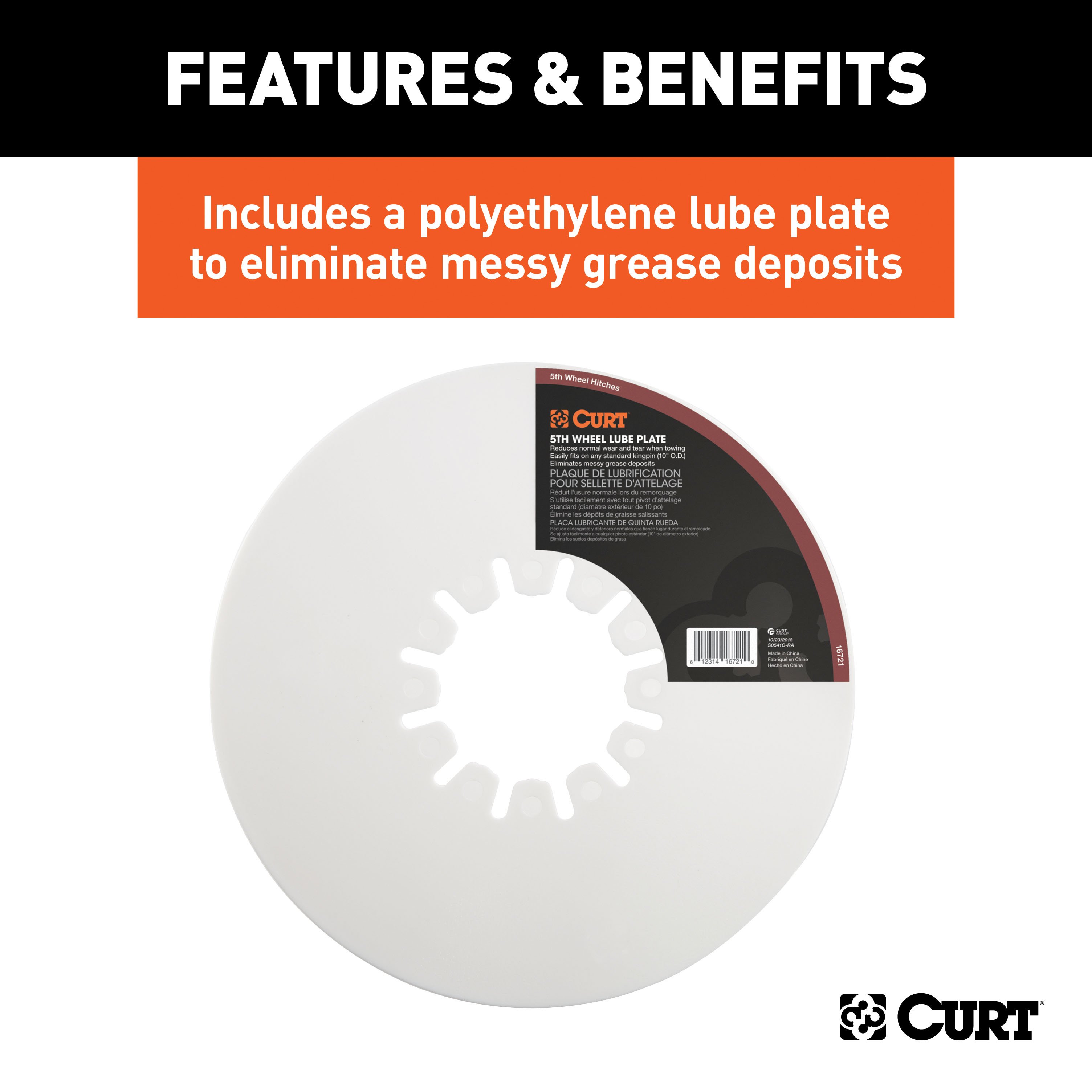
If you are using a lube plate on the trailer's kingpin, you are ready to couple. A single 3/16" thick lube plate may be used. If you are not using a lube plate, apply a high-pressure wheel bearing grease to the 5th wheel skid plate. Operating without a lube plate or grease will result in accelerated wear and/or damage to the 5th wheel's skid plate.
Back up the towing vehicle while remaining centered and aligned to the trailer's kingpin. The trailer's kingpin skid plate will compress the towing vehicle's suspension and ramp up onto the 5th wheel skid plate. During coupling: (1) The trailer kingpin fully seats into the opening on the 5th wheel head. (2) The yellow indicator will change to the green indicator (when viewing from cab). (3) The operating handle will swing rearward toward the trailer to the locked position. After coupling, visually confirm the trailer's skid plate is resting completely on the head of the 5th wheel and the jaws are locked around the trailer's kingpin.
If the kingpin is resting on top of the jaws, immediately lower the trailer jacks to lift the kingpin off the jaws. Inspect the 5th wheel for damage that may have resulted from the improper coupling attempt. Under no circumstances should the 5th wheel unit be used if damage exists. If no damage exists, review coupling instructions and repeat the procedure.
After coupling and prior to removing trailer wheel blocks and/or raising front trailer jacks, you must perform a pull test. Set the towing vehicle in a forward gear and lightly tug on the trailer to ensure that 100% coupling has taken place. If resistance is felt, release forward pressure, set the vehicle to park (if automatic) or neutral (if manual), and activate the emergency brake. If resistance is not felt, the trailer may not be coupled correctly. Do not continue applying forward pressure. Immediately stop and back the towing vehicle into the original position. Do not allow the truck and trailer to separate, as separation can cause damage and serious injury or death.
Before towing, complete the following: (1) Confirm the handle safety latch pin has been installed. (2) Attach electrical harnesses. (3) Attach lanyard and insert electric brake break-away plunger; if hydraulic surge brakes are present, attach lanyard from the surge brake assembly as required. (4) Fully retract front trailer lifting jacks. (5) Close truck tailgate or reinstall tailgate as required. (6) Remove tire chock blocks. (7) Check running lights, directional signals and brake lights for proper operation. (8) Pull forward a few feet and apply brakes to check that trailer brakes are activating. Adjust the electric brake controller if necessary.
Follow these steps: (1) Remove the safety latch pin from the handle of the 5th wheel. (2) Unlock the jaws by pulling the locking handle out about 1/2" and then swinging it forward until it latches in the unlocked position. The red unlocked indicator will be visible from the cab. (3) Remove the parking brake and slowly drive the tow vehicle out from under the trailer. If resistance is encountered, determine the corrective action and repeat uncoupling steps. (4) As the kingpin moves out of the 5th wheel jaws, the handle will drop back slightly to the couple position and the indicator will change from red to yellow. The 5th wheel hitch is now safely uncoupled and ready to be recoupled.
If the operating handle fails to latch in the unlock position while the kingpin is in the jaws, refer to the troubleshooting steps in the 'Preparation Troubleshooting' section. Never attempt to uncouple without the handle being in the unlocked position. The troubleshooting steps include: (1) Visually check for damage to the locking mechanism and ensure all components are attached and undamaged. (2) Ensure the locking mechanism is free of excessive dirt, rust, grease, snow, ice or other foreign material. Clean with warm soapy water and lightly lubricate with rust inhibitor. (3) If all components are undamaged and can freely move, apply pressure to the operating handle as if unlocking and release. (4) If cycling the handle is unsuccessful, apply pressure to the front of the jaw to manually reset the locking pawl. (5) If none of these steps resolve the issue, contact CURT Technical Service.
The A25 requires the following maintenance: (1) Skid plate: Liberally apply grease before each use and every 1,000 miles. A high-pressure wheel bearing grease is preferred, or use a lube plate. (2) Center pivot pin: Remove and apply light coating of high-pressure wheel bearing grease before each use. (3) 14mm hex pilot bolts: Torque to 100 foot lbs before each use and every 1,000 miles; re-torque after initial 500 miles. (4) 16mm head pivot bolts: Torque to 200 +/- 25 foot lbs before each use and every 1,000 miles. (5) Locking pawl: Apply small amount of grease to curved surface before each use. (6) Jaw pivot points: Use grease gun to apply grease to both zerks on front of each jaw before each use (jaws must be closed and locked). (7) Linkage pivot points: Spray small amount of rust inhibitor or lubricant on lock handle, linkage bar and pawl pivot points before each use. (8) Complete A25: Clean with warm soapy water and dry after each use; spray exposed surfaces with light coat of rust inhibitor before long-term storage.
The four 14mm hex pilot bolts must be torqued to 100 foot lbs. Re-torque after the initial 500 miles and every 1,000 miles thereafter, and prior to each individual use.
The two 16mm head pivot bolts must be torqued to 200 +/- 25 foot lbs prior to each use and every 1,000 miles thereafter.
For optimal service life, clean the A25 after each use with warm soapy water and dry with towels or compressed air. It is also recommended that the 5th wheel is removed from the vehicle or covered when not in use for extended periods of time. Before long-term storage, spray exposed surfaces with a light coat of rust inhibitor.
There are two removal options. Option 1 (complete removal): (1) Remove the four clips and mounting rail pins. (2) Remove the 5th wheel unit from the mounting rails. Option 2 (disassembled removal): (1) Remove center latch pin and large pivot pin. (2) Lift and remove head assembly and yoke. (3) Remove the rail clips and mounting pins. (4) Lift and remove mid-section and leg assembly. Note: If binding occurs, loosen the four 14mm leg mounting bolts to free them from the rails.
Reinstall the 5th wheel in the reverse order it was removed. If removal was per Option 2 (disassembled removal), follow these steps: (1) Place the mid-section, still attached loosely to the legs, into the mounting rails. (2) Insert the four mounting rail pins and clips. (3) Re-torque the four pilot hex bolts to 100 foot lbs.
Creating a gap between the trailer skid plate and the 5th wheel skid plate is not necessary or recommended. If a gap is present, it should be minimal and no more than 1/16". Excessive gap while coupled can damage internal components of the 5th wheel hitch as well as components of the trailer.
With the trailer jacks down and wheels chocked, reduce any remaining load on the jaws and kingpin by backing the tow vehicle up slightly and pushing the kingpin completely into the opening on the 5th wheel head. Hold the position by applying the vehicle's parking brake before putting the vehicle in park and releasing the standard brake.
The A25 requires truck bed base mounting rails to be installed. It is adjustable from 13" to 17" from the pickup bed to the top of its skid plate. Check with your truck's rail kit manufacturer or CURT for compatibility with your specific year, make and model.
The manual does not explicitly state whether drilling is required. It notes that when installing new bed mounting rails, the rail manufacturer's instructions should be followed, and that existing rails may need realignment. Contact CURT or your rail kit manufacturer for details.
Torque the four M14 pilot hex bolts to 100 foot lbs. Re-torque after the initial 500 miles and every 1,000 miles thereafter, and prior to each individual use.
The A25 is designed and tested at 25,000 lbs GTW. However, you must never exceed your vehicle manufacturer's recommended towing capacity or the combined tow ratings of the vehicle, hitch, and trailer.
Before each use: (1) Apply grease to the skid plate's top surface (high-pressure wheel bearing grease preferred, or use a 3/16" lube plate). (2) Remove the center pivot pin, apply light coating of grease, and replace it. (3) Apply small amount of grease to the locking pawl's curved surface. (4) Use a grease gun to apply grease to both zerks on the front of each jaw (jaws must be closed and locked). (5) Spray rust inhibitor or lubricant on the lock handle, linkage bar and pawl pivot points.
The red indicator with open jaws means the jaws are unlocked and the operating handle is latched in the unlock position. Do not tow in this configuration. The jaws will close but will not lock. To resolve: (1) Visually check for damage to the locking mechanism and ensure all components are attached and undamaged. (2) Ensure the locking mechanism is free of excessive dirt, rust, grease, snow, ice or other foreign material; clean with warm soapy water and lightly lubricate with rust inhibitor. (3) If all components are undamaged and can freely move, apply pressure to the operating handle as if unlocking and release. (4) If cycling the handle is unsuccessful, apply pressure to the front of the jaw to manually reset the locking pawl. (5) If none of these steps resolve the issue, contact CURT Technical Service at 1.877.287.8634.
If the 5th wheel handle will not latch in the unlocked position, or the red indicator is visible, follow the troubleshooting steps: (1) Visually check for any signs of damage to the locking mechanism. Ensure the jaws are open and the indicator, jaw, handle and torsion springs are all attached and undamaged. If any springs are missing or damaged, do not attempt to use the hitch until it has been repaired. (2) Ensure the locking mechanism is free of excessive dirt, rust, grease, snow, ice or other foreign material preventing it from cycling properly. Clean excessive dirt, snow, or ice with warm soapy water. Lightly lubricate exposed surfaces with a rust inhibitor to restore proper operation. (3) If all components are undamaged and can freely move, apply pressure to the operating handle as if unlocking and release. (4) If cycling the handle is unsuccessful, apply pressure to the front of the jaw to manually reset the locking pawl. (5) If none of the above steps resolve the issue, contact CURT Technical Service at 1.877.287.8634.
If the trailer is not coupling correctly: (1) Ensure the trailer height is set correctly—the kingpin skid plate should be approximately 1/2" below the top surface of the 5th wheel's skid plate lead-in ramp. (2) Verify the yellow indicator is visible and the jaws are open before attempting to couple. (3) Ensure the 5th wheel skid plate is lubricated with grease or a 3/16" lube plate is in place. (4) Back up the towing vehicle while remaining centered and aligned to the trailer's kingpin. (5) After coupling, visually confirm the trailer's skid plate is resting completely on the head of the 5th wheel and the jaws are locked around the kingpin. (6) Perform a pull test by setting the vehicle in forward gear and lightly tugging on the trailer to ensure 100% coupling has taken place. If resistance is not felt, the trailer may not be coupled correctly. Do not continue applying forward pressure; immediately stop and back the towing vehicle into the original position.
If the kingpin is resting on top of the jaws, immediately lower the trailer jacks to lift the kingpin off the jaws. Inspect the 5th wheel for damage that may have resulted from the improper coupling attempt. Under no circumstances should the 5th wheel unit be used if damage exists. If no damage exists, review the coupling instructions and repeat the procedure. This situation typically indicates the trailer height was not set correctly before coupling.
If resistance is encountered when uncoupling: (1) Ensure the handle is in the unlocked position (red indicator visible). If the operating handle fails to latch in the unlock position while the kingpin is in the jaws, refer to the troubleshooting steps: visually check for damage, ensure the locking mechanism is free of dirt/rust/grease, apply pressure to the operating handle and release, or apply pressure to the front of the jaw to manually reset the locking pawl. (2) Reduce any remaining load on the jaws and kingpin by backing the tow vehicle up slightly and pushing the kingpin completely into the opening on the 5th wheel head. (3) Remove the parking brake and slowly drive the tow vehicle out from under the trailer. If resistance persists, determine the corrective action and repeat uncoupling steps. If the issue cannot be resolved, contact CURT Technical Service at 1.877.287.8634.
| Kit # | Head Series | GTW / Vertical Load | Hitch with Standard Legs # | Head Only # | Slider Only # | Base Rails # | Height Range |
|---|---|---|---|---|---|---|---|
| Long-Bed Options | |||||||
| 16120 | A16 | 16,000 / 4,000 lbs. | 16120 | -- | -- | -- | 13" - 17" |
| 16121 | A16 | 16,000 / 4,000 lbs. | -- | 16120 | -- | 16200 | 14" - 18" |
| 16140 | A20 | 20,000 / 5,000 lbs. | 16140 | -- | -- | -- | 13" - 17" |
| 16141 | A20 | 20,000 / 5,000 lbs. | -- | 16140 | -- | 16200 | 14" - 18" |
| 16180 | A25 | 25,000 / 6,250 lbs. | 16180 | -- | -- | -- | 13" - 17" |
| 16181 | A25 | 25,000 / 6,250 lbs. | -- | 16180 | -- | 16200 | 14" - 18" |
| 16190 | A30 | 30,000 / 7,000 lbs. | 16190 | -- | -- | -- | 13" - 17" |
| 16191 | A30 | 30,000 / 7,000 lbs. | -- | 16190 | -- | 16205 | 14" - 18" |
| Short-Bed Options | |||||||
| 16052 | A16 | 16,000 / 4,000 lbs. | -- | 16520 | 16564 | -- | 17-1/2" - 21-1/2" |
| 16053 | A16 | 16,000 / 4,000 lbs. | -- | 16520 | 16564 | 16204 | 18-1/2" - 22-1/2" |
| 16352 | A20 | 20,000 / 5,000 lbs. | -- | 16540 | 16564 | -- | 17-1/2" - 21-1/2" |
| 16353 | A20 | 20,000 / 5,000 lbs. | -- | 16540 | 16564 | 16204 | 18-1/2" - 22-1/2" |
| 16551 | A25 | 25,000 / 6,250 lbs. | -- | 16580 | 16574 | -- | 17-1/2" - 21-1/2" |
| 16553 | A25 | 25,000 / 6,250 lbs. | -- | 16580 | 16574 | 16204 | 18-1/2" - 22-1/2" |
No reviews have been added for this product.