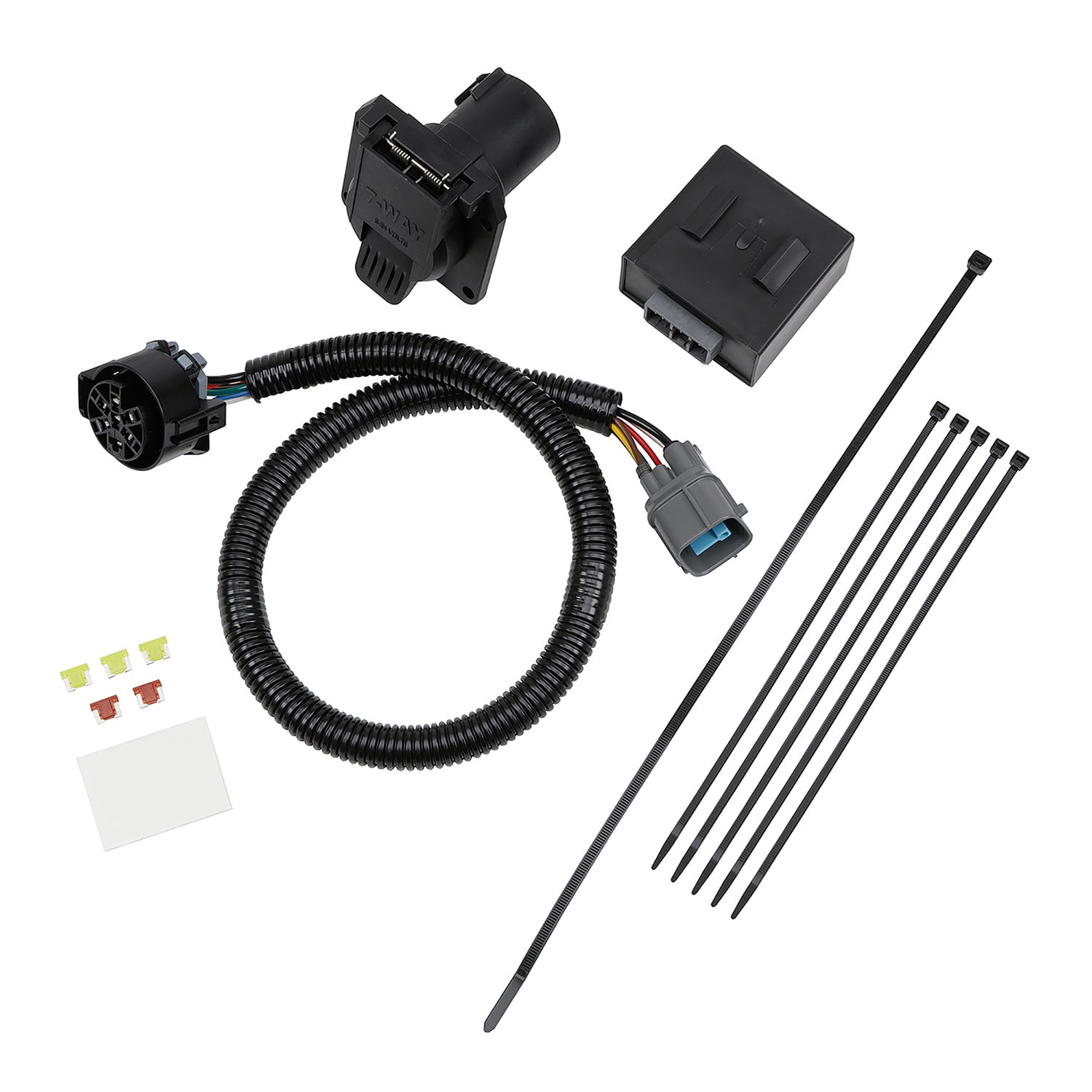
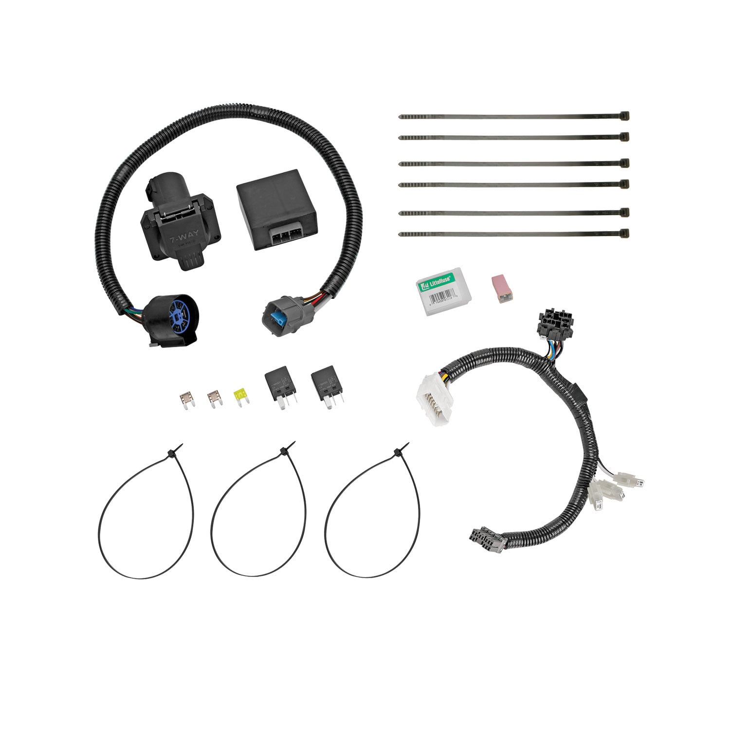
Tekonsha Tow Harness, 7-Way, w/Circuit Protected ModuLite HD Module TK118289TekonshaOriginal price was $135.00. Current price is $117.79.In Stock
View productOur in-house experts typically reply within one business day.

Tekonsha
On Sale Today
Original price was $278.75. Current price is $210.84.You save $67.91 (24%)
Free Shipping
Ships free on all orders
 Authorized Dealer



Always the correct part
We know our products
Quality Products
Free Shipping!
Always the correct part
We know our products
Quality Products
Free Shipping!
FREE ShippingFREE SHIPPING
Estimated delivery Sun, Oct 11 - Wed, Oct 14
Order before 2 PM EST Monday–Friday for same-day processing
Guaranteed safe & secure checkout

No other product is designed to specifically deliver everything needed for a fully functional 7-Way, INCLUDING a brake control plug. No more piecing together products. These kits are custom made and will REDUCE the installation time of installing a fully functional 7-Way.
| WEIGHT: | 6.15 LBS |
| UNIVERSAL OR SPECIFIC FIT: | SPECIFIC |
| CIRCUIT PROTECTED: | YES |
| HARNESS TYPE: | MALE FEMALE |
| TERMINAL QUANTITY: | 7 |
| WIRE COLORS: | BROWN, GREEN, YELLOW, WHITE |
| WIRE QUANTITY: | 7 |
| WIRE GAUGE: | 18 AWG, .85 AVSS |
| POWER LEAD REQUIRED: | YES |
| ELECTRICAL SYSTEM TYPE: | UNIVERSAL |
| HARDWARE INCLUDED: | YES |
| AMPERAGE: | 30 A |
| BRAND: | TEKONSHA |
| PART NUMBER: | 22551 |
| WARRANTY: | LIMITED 1 YEAR WARRANTY |


Tekonsha is a leading manufacturer of electronic trailer brake controllers, pioneering the category in the 1970s. The lineup spans proportional units such as the Prodigy P3 and Prodigy iD, time-delayed controllers, the wireless Prodigy RF, plus vehicle-specific wiring harnesses, adapters and trailer brake components engineered for smooth, predictable stopping at any speed.
Tekonsha Engineering Company began in 1964 building RV steps and mirrors. Within a few years it had found its real calling, and by the 1970s Tekonsha was pioneering the manufacture of electronic trailer brake controllers, the product category that still defines the brand. More than half a century later it remains the reference name in trailer braking and is part of the Horizon Global group alongside Reese, Draw-Tite, Fulton, Bulldog and Wesbar.
A brake controller is the component that tells a trailer's electric brakes how hard to work and when, and getting that right is the difference between a controlled stop and a shove from behind. Tekonsha builds both major types. Proportional controllers use an internal accelerometer to sense how quickly the tow vehicle is slowing and apply trailer braking to match, so light braking stays light and hard braking is immediate. Time-delayed controllers ramp to a preset output over a fixed interval, a simpler and more economical approach that suits occasional towing.
The current brake controller range covers most of that ground. The Prodigy iD pairs with a phone through Tekonsha's EDGE technology for setup and monitoring, the P3 offers storable settings for multiple trailers and a trilingual colour LED display, the Prodigy P2 adds a dimmable display and boost mode for heavier loads, and the Voyager keeps operation simple and dependable. The Prodigy RF mounts to the trailer itself and controls wirelessly, which suits rental fleets and drivers who swap tow vehicles.
Installation is supported by vehicle-specific brake control harnesses that plug into a factory connector rather than requiring cut-and-splice wiring, along with mounting brackets and adapters. Matched controller bundles pair a unit with the correct harness. Products are tested to meet and often exceed published industry standards.
Experts available to answer your questions
Call 888-634-94941 Year
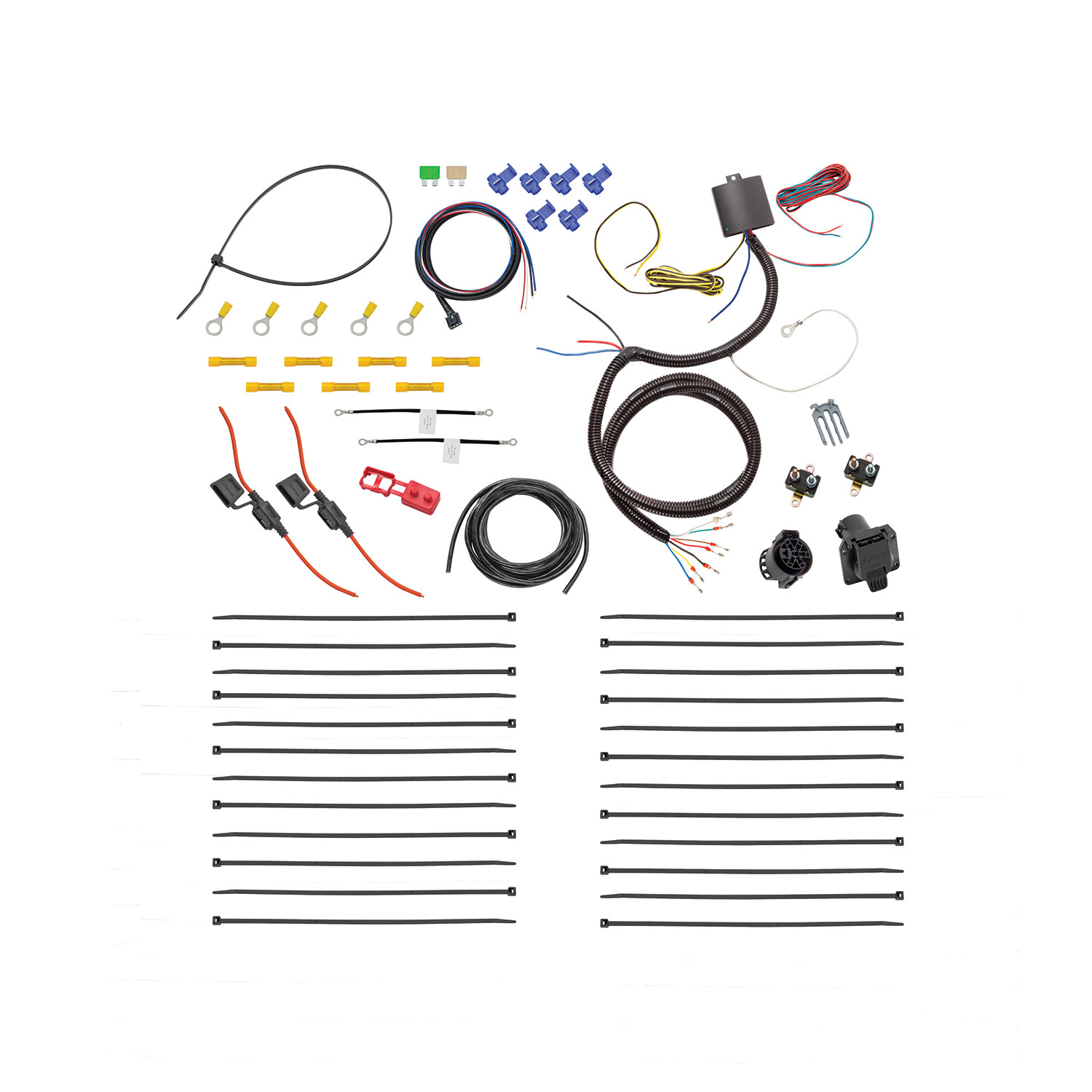
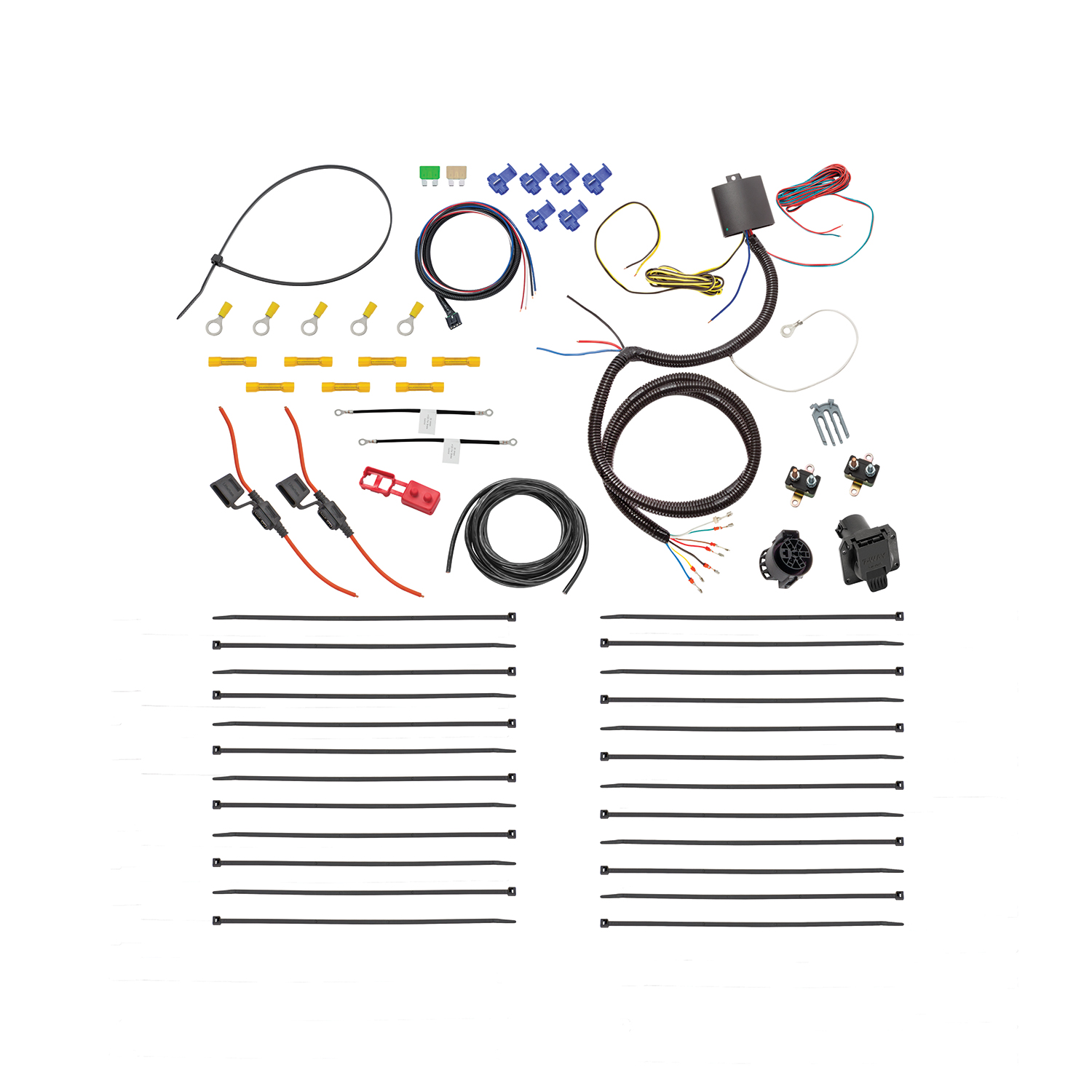
The Tekonsha 22551-037 is a plug-and-play tow harness kit that connects a tow vehicle's electrical system to a trailer. It includes a power module, 7-way harness, brake control harness, fuses, connectors, and all necessary hardware. Approximate installation time is 120 minutes.
The kit is designed for vehicles with 2-wire, 3-wire, BT multiplex, or BTT multiplex wiring systems. However, the module may not work with some BTT wiring systems; in those cases, you may need to route the tail wire to the rear license plate illumination circuit and/or brake to the center high stop light.
Required tools are: Phillips head #2 screwdriver, wire cutters, wire strippers/crimpers, and a tester or volt meter. No power tools or drilling equipment is mentioned as required.
Yes. The manual requires you to disconnect and isolate the vehicle's negative battery terminal before splicing the tow harness input wires to the vehicle.
Yes, one 3/32" hole must be drilled for the chassis ground connection. The manual specifies drilling into a suitable grounding point near the vehicle frame or crossmember, and explicitly states: do not drill into the vehicle floor or bed.
The power fuse is rated 15 AMP MAX. The kit includes a 25 AMP fuse for the module B+ circuit and a 30 AMP fuse for the 7-way B+ circuit. Do not exceed circuit capacity: max 2 stop/turn/backup lights per side (4.2 amps), max tail lights (12 amps), max 7-way 12V+ (30 amps).
The blue wire taps provided are for 16-18 gauge wire only. When splicing, use appropriate gauge wire splices for your vehicle's wiring.
Wear safety glasses during installation. Do not probe across two wires or across vehicle structure when testing. Avoid routing wires near hot pipes, heat shields, or fuel tank. Mount the module with the epoxy side facing ground to prevent water buildup. Overloading the circuit can cause fires.
The kit includes: tow harness, power module, power fuse (15 AMP MAX), 7-way harness and socket, brake control harness, 24 cable ties (8.5"), 1 cable tie (14.5"), 6 wire taps, 1 foam tape, 1 25 AMP fuse, 1 30 AMP fuse, 4 ring terminals, 2 fuse holders, 7 yellow butt connectors, 1 self-tapping screw, 1 breaker boot, 2 wire assemblies, 1 20 AMP circuit breaker, and 1 30 AMP circuit breaker.
No. The manual states the bracket is not included. You must source a suitable bracket separately to mount the 7-way socket at your chosen location.
No. The brake control is not included. The kit includes only the brake control harness, which is designed to work with Tekonsha brake controls such as models 90195, 90885, or 90160. You must purchase a compatible brake control separately.
The manual provides a wiring system determination table with five types: A (2-wire: turn and brake combined, tail and reverse separate), B (3-wire: all functions separate), BT (brake/tail combined, turns separate, reverse separate), and BTT (brake/tail/turn combined, reverse separate). Use a volt meter or circuit tester to probe each wire at a time—do not probe across two wires or vehicle structure—and match the voltage patterns to the table to identify your system type.
The module may not work with some BTT wiring systems. If you experience issues, you may need to route the tail wire to the rear license plate illumination circuit and/or the brake wire to the center high stop light. Consult the vehicle's owner's manual and instruction sheet for the location of these circuits.
Mount the module on the driver's side using the double-sided tape provided. Ensure the epoxy side of the module is pointed towards the ground to prevent water buildup.
Locate a suitable grounding point near the adapter, such as the vehicle frame or crossmember. Do not drill into the vehicle floor or bed. Clean dirt and rustproofing from the area, drill a 3/32" hole, and secure the white wire using the eyelet and screw provided.
1. Disconnect and isolate the vehicle's negative battery terminal. 2. Determine your vehicle's wiring system type using a volt meter. 3. Mount the power module on the driver's side using double-sided tape. 4. Drill a 3/32" hole and secure the white ground wire to the vehicle frame. 5. Splice the tow harness input wires to the vehicle according to your wiring system type. 6. Route the body harness from the module forward, connecting the black wire (7-way B+) to the positive battery terminal via a 30 AMP fuse holder, and the red wire (module B+) to the positive battery terminal via a 25 AMP fuse holder. 7. Connect the blue wire (electric brake output) to the brake control harness. 8. Mount and wire the brake control harness, routing the white wire to ground and the black wire to the positive battery terminal via a 30 AMP circuit breaker. 9. Route the red brake wire to the cold side switch of the brake pedal. 10. Determine and mount the 7-way socket at your chosen location. 11. Secure all harnesses with cable ties. 12. Reconnect the vehicle's negative battery cable. 13. Test and verify installation with a test light or trailer.
Route the black wire (7-way B+) from the body harness to the vehicle's positive battery terminal. Use a 30 AMP fuse holder, butt connector, and ring terminal to make the connection. Route the red wire (module B+) to the positive battery terminal using a 25 AMP fuse holder, butt connector, and ring terminal.
1. Determine a suitable mounting point on the tow vehicle for the brake control harness. 2. Secure the brake harness near the desired brake control mounting location. 3. Route the white wire to an existing common ground or directly to the vehicle battery negative side. 4. Route the black wire to the vehicle's positive battery terminal using a 30 AMP circuit breaker, breaker boot, wire assembly, butt connector, and ring terminal. 5. Route the red wire to the cold side switch of the brake pedal using the supplied wire tap or best suited alternative.
Use the included 20 AMP circuit breaker when towing trailers with one to three axles. For other trailer configurations, use the 30 AMP circuit breaker.
Beginning at the module, route the body harness toward the vehicle's front. Route the wire carefully to avoid hot pipes, heat shields, the fuel tank, or any other points that may pinch or break the wire. Secure the harness with the cable ties provided, being careful to avoid areas that would pinch, cut, or melt the wire.
1. Determine the 7-way mounting location. 2. Route the 7-way harness containing the 7 wires towards the mounting location. 3. Pin the housing according to the 7-way diagram. 4. Connect the 7-way harness and 7-way socket. 5. Mount the 7-way assembly (note: bracket is not included).
The 7-way harness contains: Black = +12V battery, Brown = tail lights, Yellow = left turn, Green = right turn, Red = stop/brake, Blue = backup/reverse, and White = chassis ground.
For a 2-wire system (turn and brake combined on one wire, tail and reverse on separate wires): connect yellow to the vehicle's left turn/brake wire, green to the right turn/brake wire, brown to the tail wire, and blue to the reverse wire. The red brake wire is not used.
For a 3-wire system (all functions on separate wires): connect yellow to the vehicle's left turn wire, green to the right turn wire, brown to the tail wire, red to the brake wire, and blue to the reverse wire. All wires are used.
For a BT multiplex system (brake and tail combined, turns separate, reverse separate): connect yellow to the vehicle's left turn wire, green to the right turn wire, red to the brake/tail wire, and blue to the reverse wire. The brown tail wire is not used.
For a BTT multiplex system (brake, tail, and turn combined on one wire, reverse separate): connect yellow to the vehicle's brake/tail/left turn wire, green to the brake/tail/right turn wire, and blue to the reverse wire. The brown tail wire and red brake wire are not used. Note: the module may not work with some BTT systems; if issues occur, route the tail wire to the rear license plate illumination circuit and/or brake to the center high stop light.
When using a volt meter or circuit tester, carefully probe one wire at a time. Do not probe across two wires or across vehicle structure. Determine the type of vehicle wiring system and location of required input functions, then determine each of the tow vehicle inputs as shown in the illustration.
After reconnecting the vehicle's negative battery cable, test and verify the installation with a test light or by connecting an actual trailer. This confirms that all lights and brake functions are working correctly.
Do not exceed: maximum 2 stop/turn/backup lights per side (4.2 amps total), maximum tail lights (12 amps), maximum 7-way 12V+ (30 amps). Overloading the circuit can cause fires. Consult the vehicle's owner's manual and instruction sheet for additional information.
Route wires carefully to avoid hot pipes, heat shields, the fuel tank, or any other points that may pinch or break the wire. Secure the harness with cable ties provided, being careful to avoid areas that would pinch, cut, or melt the wire.
The epoxy side must face ground to prevent water buildup inside the module, which could damage the electrical components.
First, ensure input wires are installed correctly according to your vehicle's wiring system type (A, B, BT, or BTT). Remove the 25 AMP fuse for 10 seconds and repeat the test. If the problem continues, ensure the blue wire taps are installed correctly. Using a tester or volt meter, check for voltage on each input wire near the module. Remove the 25 AMP fuse for 10 seconds and repeat the test.
Possible causes are: (1) Poor chassis ground—ensure the ring terminal is in full contact with bare metal of the vehicle's chassis; (2) Circuit protection activated—remove the 25 AMP fuse for 10 seconds and repeat the test; (3) Faulty or loose fuse—ensure the 25 AMP fuse is fully inserted into the fuse holder with no breaks; (4) Fuse holder not connected to battery—verify the fuse holder is connected properly to the positive post of the battery; (5) Module not receiving power—check for voltage on either side of the yellow butt connector near the module. For each issue, remove the 25 AMP fuse for 10 seconds and repeat the test.
Ann
Ordered online. Shipment arrived on time and with all the correct parts. Great customer service and friendly staff. Also, pricing was great!
May 22, 2023