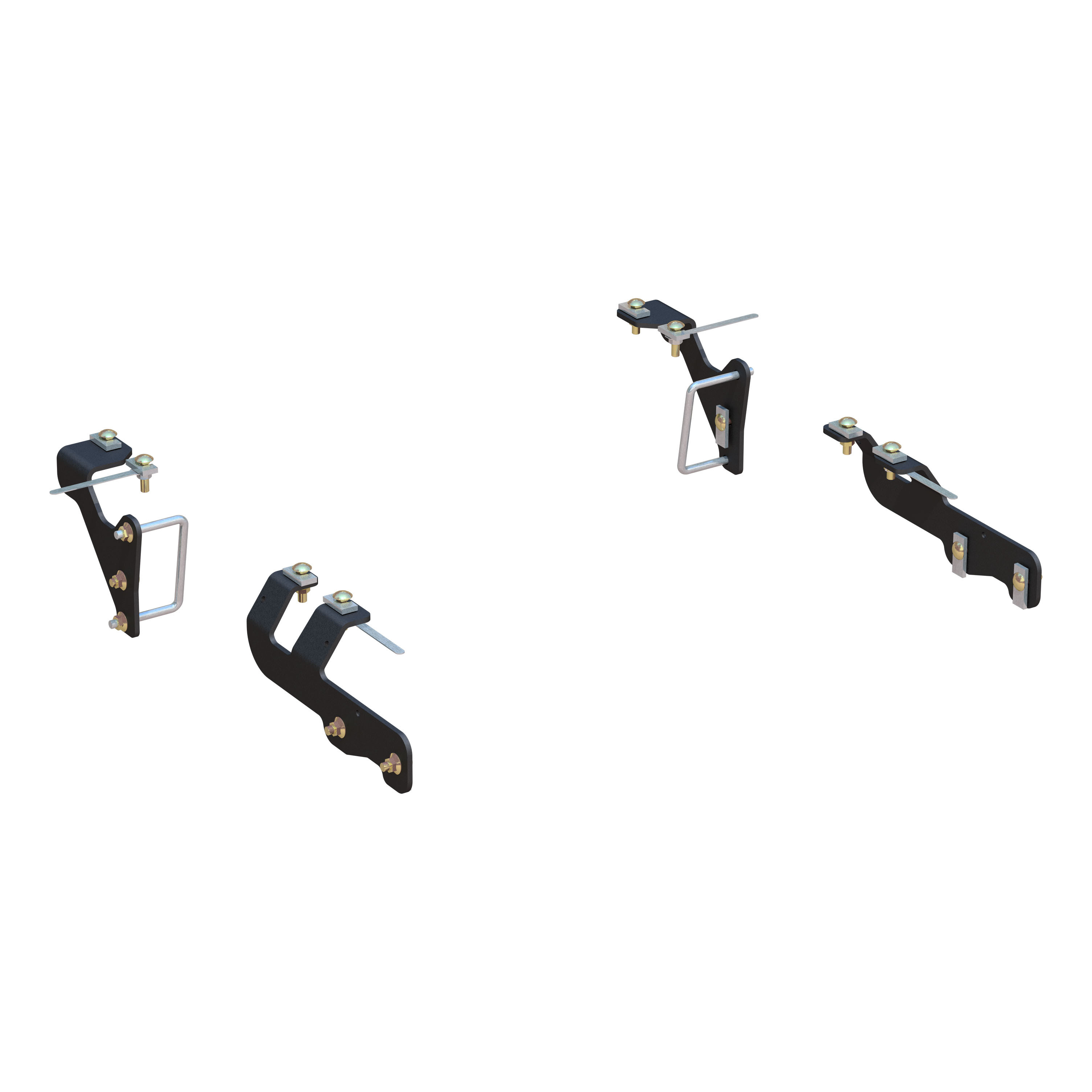
CURT Custom 5th Wheel Brackets, Select Ram 1500 Fifth Wheel Trailer Hitch BracketCURTOriginal price was $349.95. Current price is $220.99.In Stock
View productOur in-house experts typically reply within one business day.

CURT
On Sale Today
Original price was $404.95. Current price is $255.99.You save $148.96 (37%)
Free Shipping
Ships free on all orders
 Authorized Dealer
2013 - 2017 Ram 1500
Confirmed to Fit
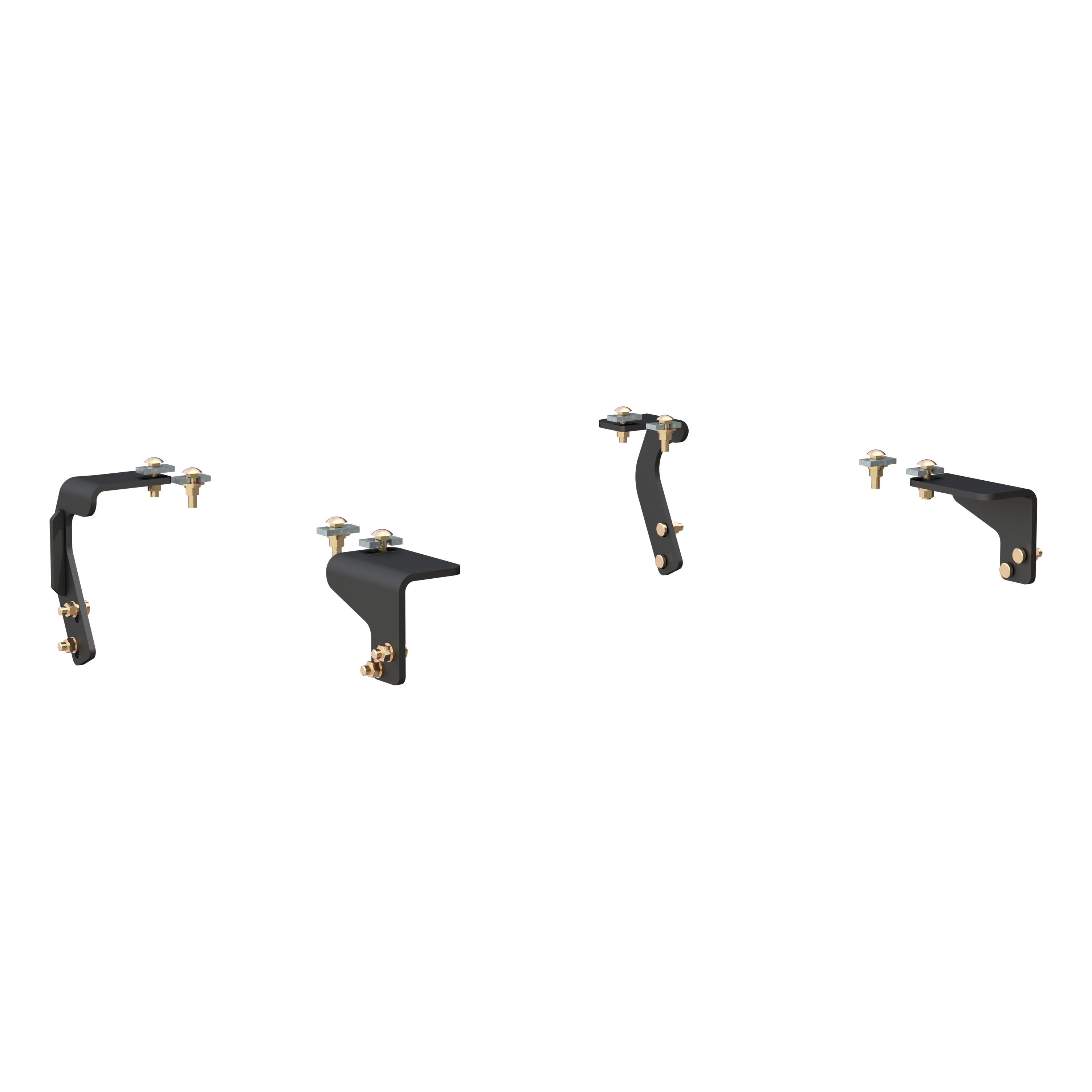
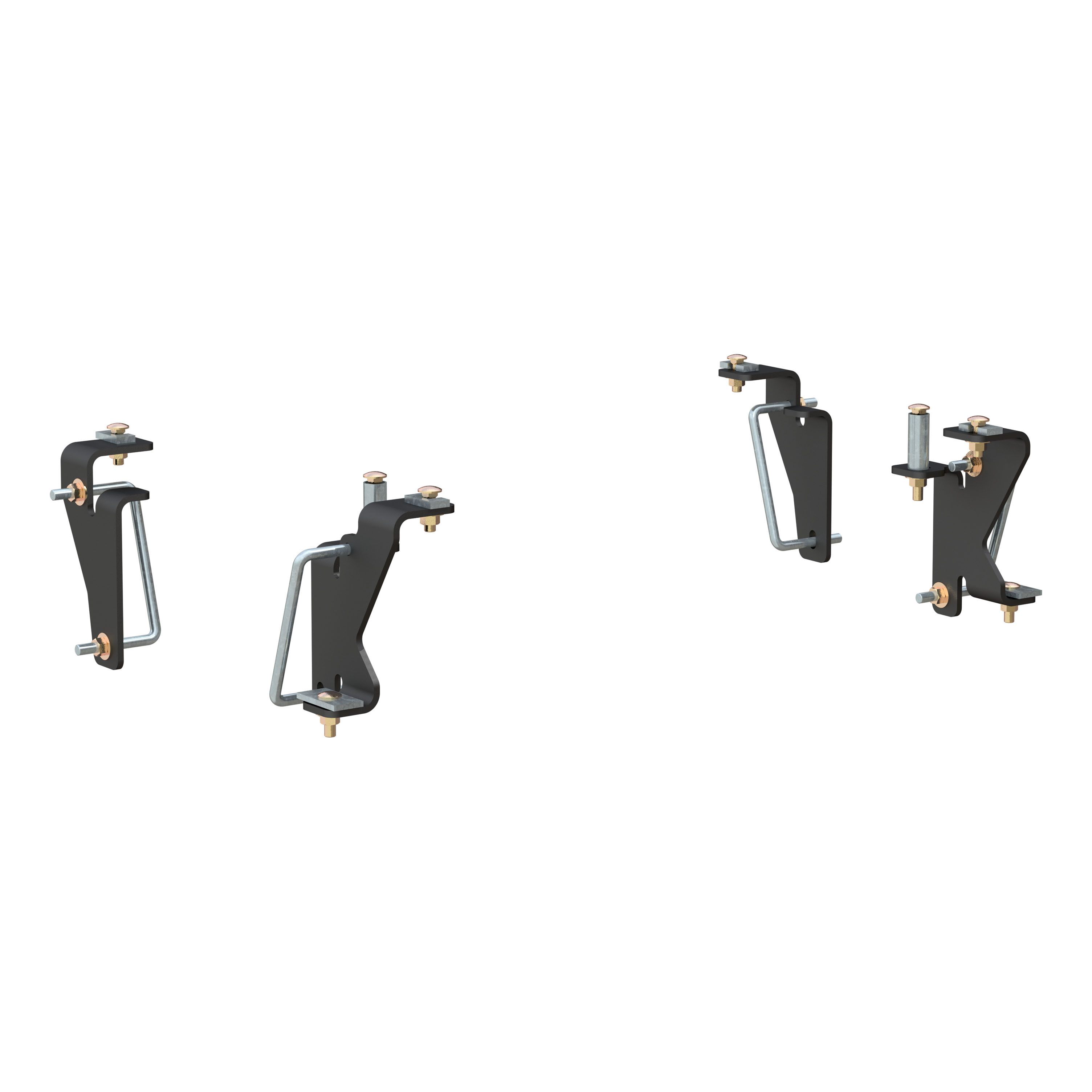


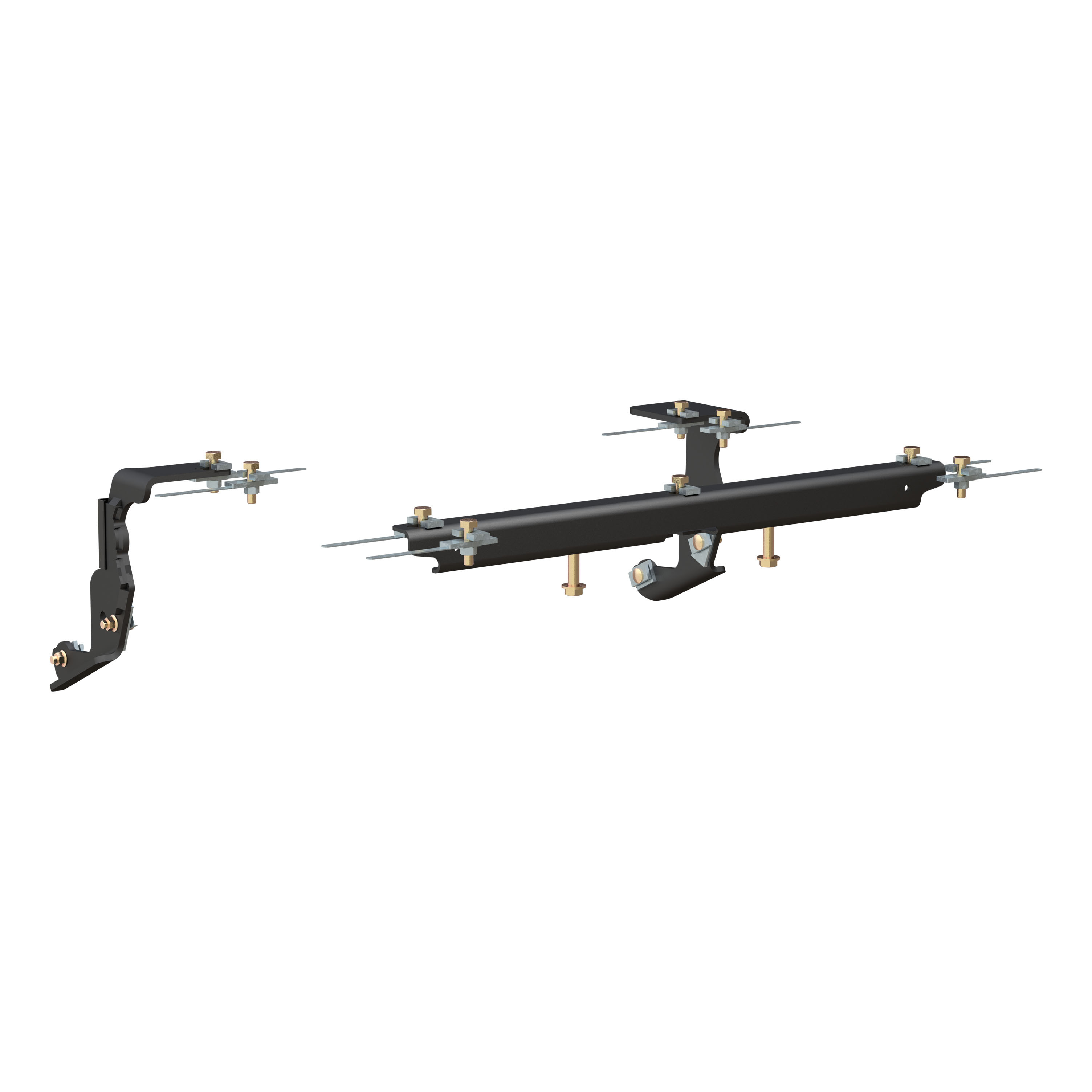


Always the correct part
We know our products
Quality Products
Free Shipping!
Always the correct part
We know our products
Quality Products
Free Shipping!
Verify Fitment
Select your vehicle to confirm this part fits.
Quick Ship
In stock and ready to ship — order now!
Shipping from Eau Claire, WIFREE SHIPPING
Estimated delivery Mon, Sep 28 - Wed, Sep 30
Order before 2 PM EST Monday–Friday for same-day processing
Guaranteed safe & secure checkout
Total for 2 items:
$380.94$541.90
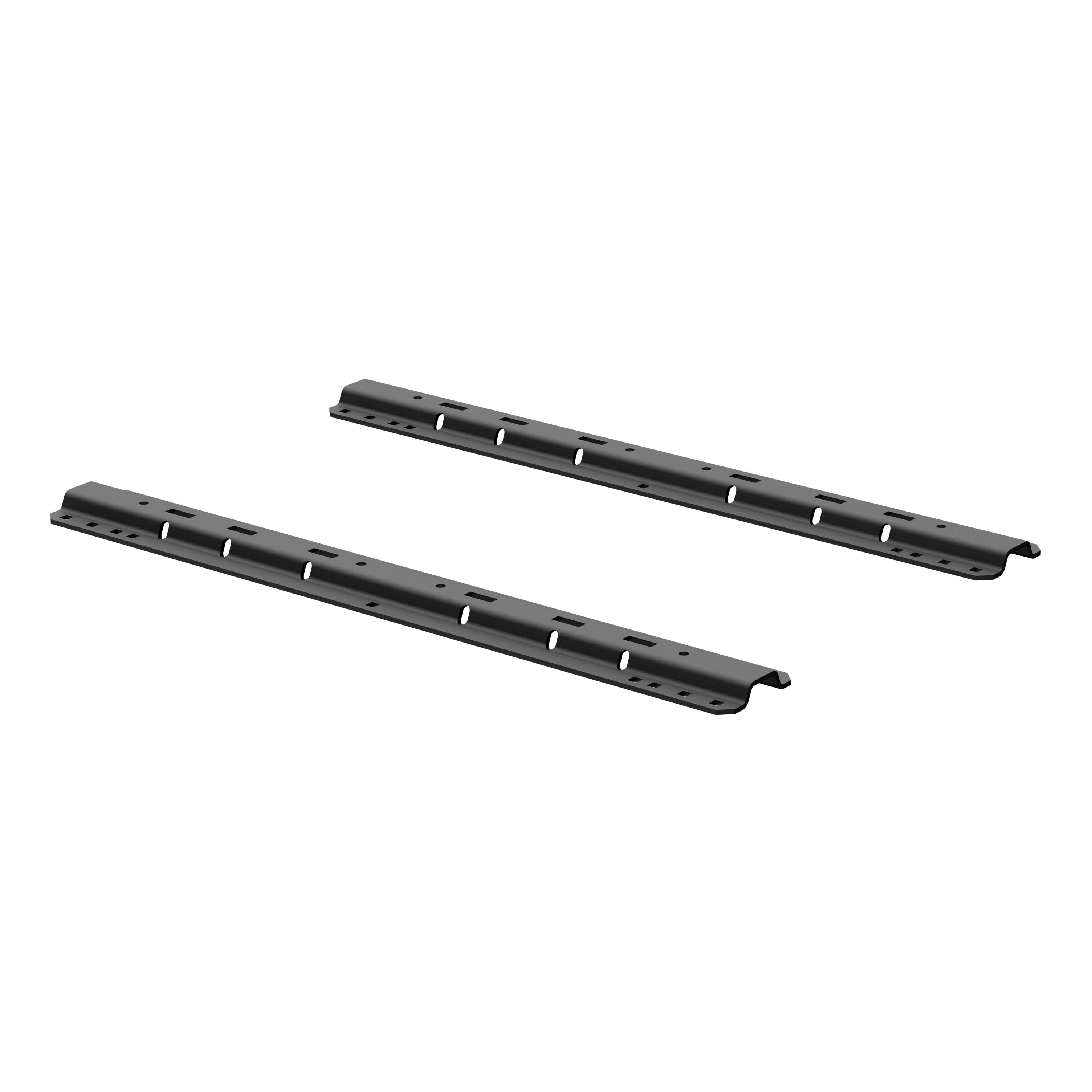
Base rails sold separately

Warranty: Limited Lifetime Warranty (One-Year Finish, One-Year Parts)
Finish: A-COAT
Installation Time Exact (Minutes): 0
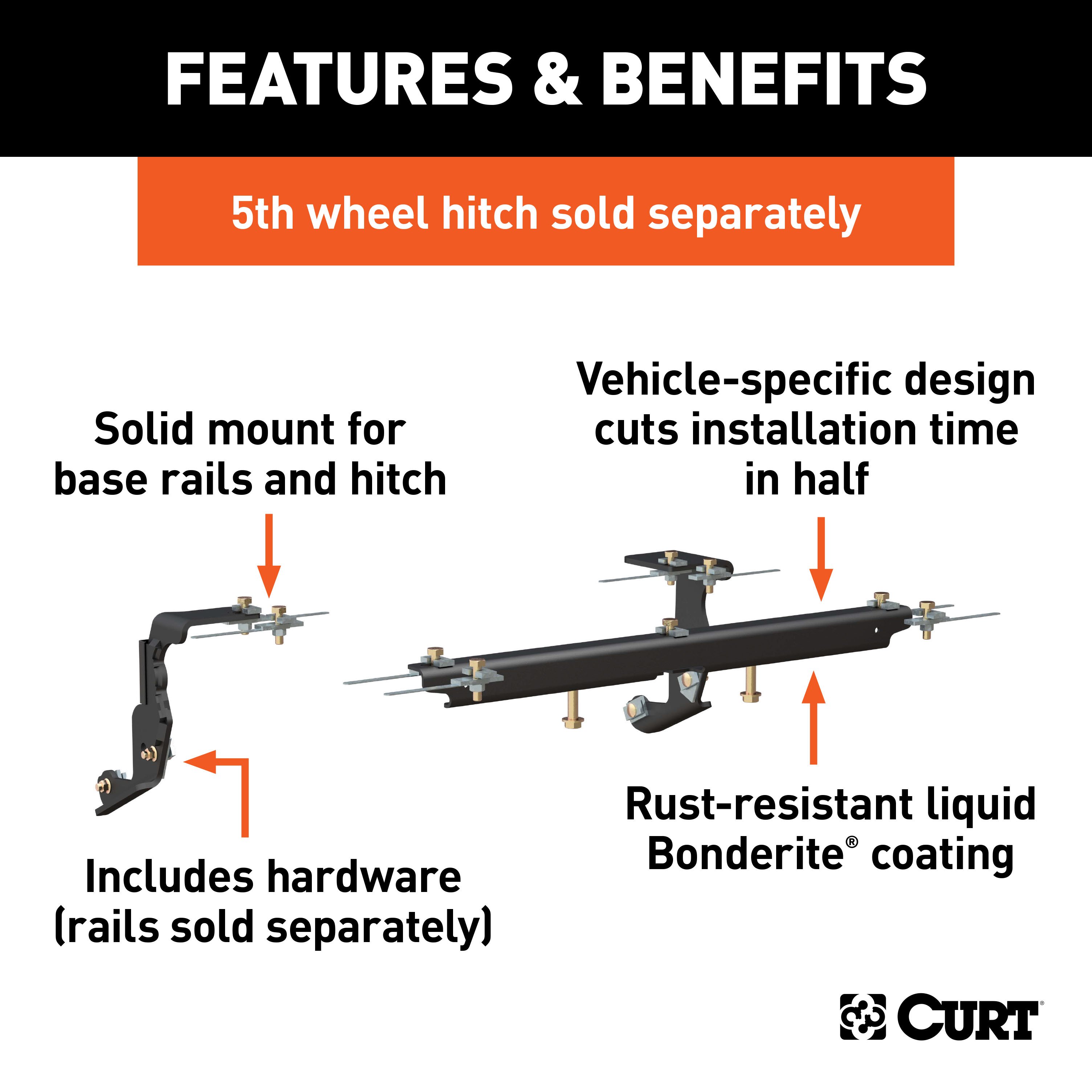
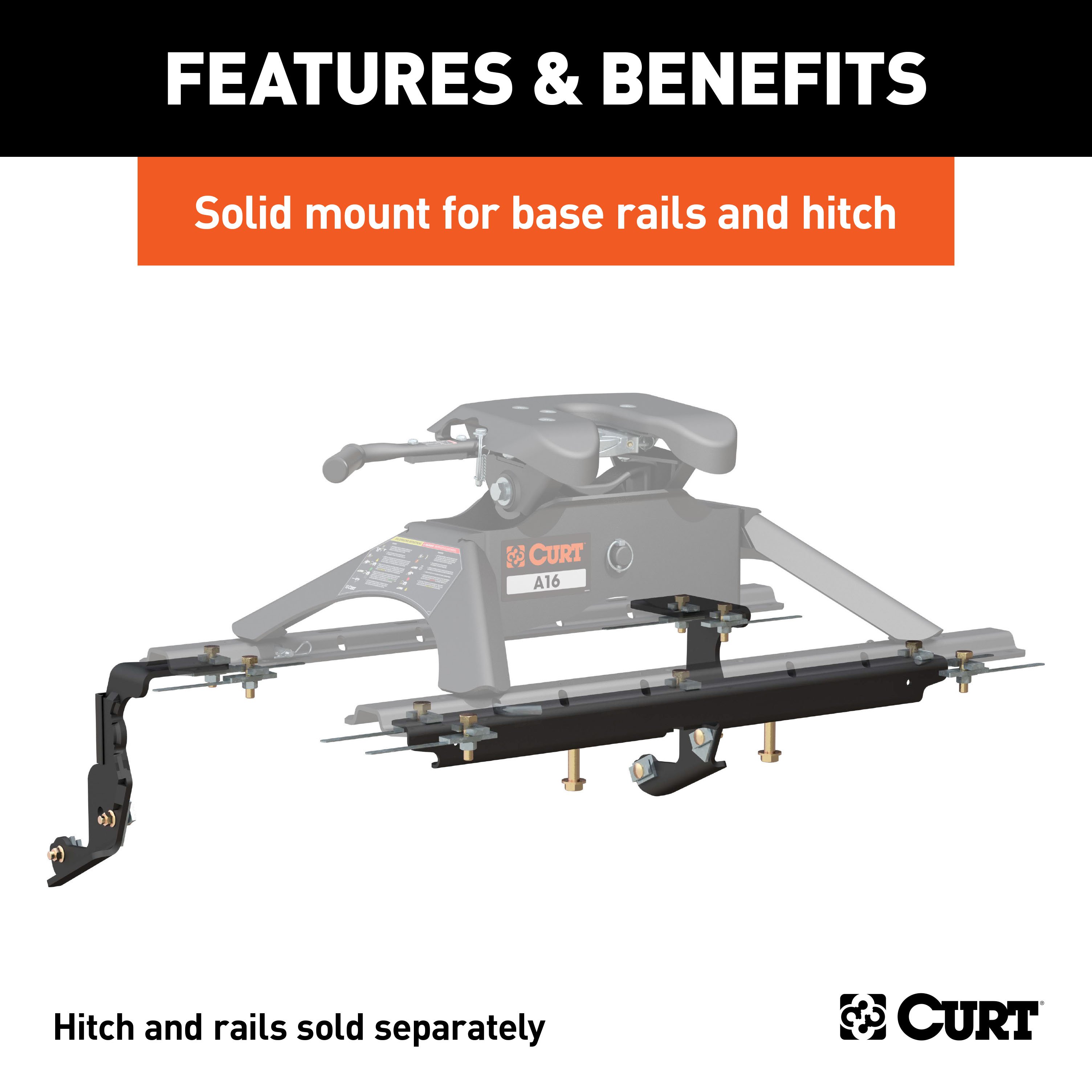
When you purchase a 5th wheel trailer hitch, you expect it to be capable of towing your RV, flatbed or whatever other 5th wheel trailer you own. While a 5th wheel hitch does offer an impressive amount of towing strength, it cannot get far without the proper installation equipment. Engineered for specific makes and models, CURT custom 5th wheel brackets provide the ideal solution for complementing the power of your 5th wheel trailer hitch. A custom 5th wheel bracket features a shape that contours to the frame of your truck and uses pre-drilled holes in the frame wherever possible to make installation quick and easy. Depending on your model of pickup truck, they also reduce or eliminate the need for drilling. These particular custom 5th wheel brackets offer a custom fit for certain model years of the Ram 1500 with factory air suspension (see application info to verify fitment). Finished in a durable liquid A-coat, CURT custom 5th wheel brackets are made to last. They include all necessary mounting hardware and are designed to be used in conjunction with CURT industry-standard 5th wheel base rails #16104 or #16204 (base rails sold separately).

CURT offers a variety of high-quality trailer hitches and accessories for select vehicle models. Find the perfect fit for your towing needs at TowUniverse.
CURT, a Lippert brand, offers a complete line of towing products and is the leading manufacturer of custom-fit trailer hitches. We offer the broadest selection of custom-fit hitches, and each one is designed, welded, and coated in Wisconsin.
CURT is also a leader in flat towing products, as well as 5th wheel, gooseneck, and weight distribution hitches, ball mounts, electrical components, cargo solutions, and other towing accessories.
For everything from passenger cars and vans to full-size pickups and SUVs, CURT is 'The First Name in Towing Products®.'
Experts available to answer your questions
Call 888-634-9494Rediscover "Us" Time | Tested. Proven. Safe. Towing Products
Yes, the CURT Custom 5th Wheel Brackets, Select Ram 1500 with Factory Air Suspension Fifth Wheel Trailer Hitch Bracket (Part #BKDK16444) is designed to fit the 2013-2017 Ram 1500.
The CURT Custom 5th Wheel Brackets, Select Ram 1500 with Factory Air Suspension Fifth Wheel Trailer Hitch Bracket (Part #BKDK16444) fits the following vehicles: 2013-2017 Ram 1500. Always verify your specific year, make, and model before ordering.
The CURT Custom 5th Wheel Brackets, Select Ram 1500 with Factory Air Suspension Fifth Wheel Trailer Hitch Bracket (Part #BKDK16444) fits 2013-2017 Ram 1500 models. The 2017 model year is the last year covered by this part number. For newer models, check for an updated version.
The CURT Custom 5th Wheel Brackets, Select Ram 1500 with Factory Air Suspension Fifth Wheel Trailer Hitch Bracket (Part #BKDK16444) Drilling is required for installation. Typical installation time is . Basic hand tools are typically all you need.
The Curt 16444 is designed for Dodge/Ram 1500 vehicles. However, installation varies by truck bed length (67", 76", or 96"), which affects mounting rail spacing and hole locations. Dual exhaust vehicles require additional steps to remove and reattach the driver-side exhaust hanger. Consult the manual's bed-length-specific drilling instructions (page 5) to confirm your truck configuration is supported.
The C-channel must be slid between the spare tire and rear axle during installation (step 11), so clearance is required. The manual does not specify minimum spare tire size or location restrictions, but the installation process assumes the spare tire can be temporarily moved or worked around. If your spare tire is mounted in an unusual location, contact Curt Manufacturing to confirm fitment.
Yes. Dual exhaust vehicles require additional steps: unbolt the driver-side exhaust hanger from the cross-member and remove it before C-channel installation (step 10), then reattach it after the C-channel is secured (step 15). The C-channel is positioned over the exhaust on the passenger side, so the driver-side hanger must be temporarily removed to allow proper placement.
The kit includes: 4× 1/2-13 UNC 1-3/4" grade 8 bolts; 10× 1/2-13 UNC 2" grade 8 hex head cap screws; 2× 5/8-11 UNC 3-1/2" grade 8 hex head cap screws; 4× 1/2-13 UNC serrated flange nuts; 2× 5/8-11 UNC serrated flange nuts; 10× 1/2-13 UNC handle nuts; 2× 5/8" flat washers; 2× 0.250×1.50×3.00" square hole spacers; 10× 0.250×1.00×3.00" square hole spacers; 4× 0.250×1.00×2.00" square hole spacers; 2× 0.250×1.50×2.00" round hole spacers; 10× 0.313×1.00×2.00" U-shape spacers; 3× cable ties; 2× 1/2" fishwire; and 1× edge trim. See page 1 for complete hardware list.
The manual specifies a drill is required to enlarge pre-drilled holes from 3/16" to 17/32" (steps 12 and 17). A center punch is needed to mark hole locations (step 16b). The manual does not list other required tools such as wrenches, sockets, torque wrench, or lifting equipment. Contact Curt Manufacturing or a professional installer if you need a complete tool list.
Yes. The manual explicitly states "Remove wheel well liners" as a required preparation step. These must be reinstalled after the hitch installation is complete (step 20).
Before installation, you must: remove wheel well liners; unbolt and remove the driver-side exhaust hanger (dual exhaust vehicles only); disconnect electrical connectors from the driver and passenger side behind the cross member; remove the rear differential breather tube from the vehicle frame cross member and shock mount; and temporarily remove plastic clips holding the wiring harness to the top of the vehicle frame cross member. All of these are reinstalled after the C-channel is secured (steps 11, 15, and 20).
The C-channel must be slid between the spare tire and rear axle over the exhaust on the passenger side. Rest the driver side end on the bump stop mount and the passenger side end on the exhaust pipe (rear of muffler). Raise the driver side end over the vehicle frame; it may need to slide to the passenger side between the passenger side frame rail and suspension. While raising the passenger side end, slide the C-channel to the driver side. Use caution with air lines to prevent damage. Before final positioning, insert the passenger side wiring harness plastic clip through the large hole in the C-channel and between the bed sill and cross member. Slide into final position and secure the rear differential breather tube with a zip tie through the large hole (step 11).
The forward and rear mounting rails must be spaced 22" on center (step 16b). This spacing is verified by placing the forward mounting rail in the bed and measuring 22" from the forward to rear rails, then centering the rail side to side before drilling.
The mounting rails must be centered between the box sides on the length of the truck box floor (step 16a). If using a hitch attachment, position the forward mounting rail by inserting its tabs into the mounting rail and pushing it tight towards the rear rail. If no hitch attachment is available, place the forward rail in the bed, measure 22" on center from forward to rear rails, and center the rail side to side. Use center punch to mark Row 2 hole locations before drilling to verify alignment due to bed support location variances (step 16b).
Yes. Drilling is required. The manual explicitly states "Drilling required" in the installation notes. You must enlarge pre-drilled 3/16" holes to 17/32" in the vehicle frame cross member (step 12) and in the truck bed (step 17). You must also drill new 3/16" holes in the truck bed at Row 1 and Row 2 locations (step 16a or 16b), then enlarge these to 17/32". Additionally, drill a 1" access hole in the bottom of the bed sill (page 5). These modifications are permanent.
Hole locations depend on your truck bed length: for 67" and 76" boxes, the rear edge of the mounting rail should be 29" from the rear edge of the truck bed; for 96" boxes, it should be 31" from the rear edge. You must drill 2 center holes in addition to 8 holes for mounting plates and other hardware. Choose 10 holes identified by black dots that correspond with your vehicle configuration (page 4). Row 1 and Row 2 holes must be drilled at 3/16", then enlarged to 17/32" (steps 16a, 16b, and 17). See page 5 for the drilling diagram.
Yes. You must drill a 1" access hole in the bottom of the bed sill (page 5). This hole is used to install 1/2" carriage bolts, U-shaped spacers, and fasteners that secure the mounting plates to the truck bed.
You must drill 3/16" holes initially in the vehicle frame cross member and truck bed (steps 12, 16a, 16b). These 3/16" holes are then enlarged to 17/32" (steps 12 and 17). Additionally, drill a 1" access hole in the bottom of the bed sill (page 5). The manual does not specify hole sizes for other components; refer to the hardware list and drilling diagram for complete details.
Yes. The manual explicitly states "Relocate rear diff. breather tube and wiring" as a required modification. You must remove the rear differential breather tube from the vehicle frame cross member and shock mount (step 11), then reposition it after the C-channel is installed. Secure it with a zip tie through the large hole in the C-channel (step 11). Reinstall the wiring harness and breather tube after all frame and rail fastening is complete (step 20).
Yes. After enlarging the 3/16" holes to 17/32" in the vehicle frame cross member, paint bare metal as needed (step 12). After enlarging the 3/16" holes to 17/32" in the truck bed, paint bare metal as needed (step 17). This protects the exposed metal from rust.
Torque all 1/2" fasteners to 110 lb-ft and all 5/8" fasteners to 180 lb-ft (step 19). The torque sequence is: first torque the hex bolts that fasten the rails to the frame brackets through the bed, then torque the hex bolts positioned in the center of the rails, then torque the fasteners that attach the frame brackets to the vehicle frame, then all remaining fasteners.
All 1/2" fasteners must be torqued to 110 lb-ft (step 19).
All 5/8" fasteners must be torqued to 180 lb-ft (step 19).
The torque sequence is: (1) torque the hex bolts that fasten the rails to the frame brackets through the bed; (2) torque the hex bolts positioned in the center of the rails; (3) torque the fasteners that attach the frame brackets to the vehicle frame; (4) torque all remaining fasteners. Torque all 1/2" fasteners to 110 lb-ft and all 5/8" fasteners to 180 lb-ft (step 19).
Use U-shaped spacer plates (CM-SP136) between the C-channel or mounting rail and the truck bed to ensure metal-to-metal contact (step 14). Use U-shaped spacer plates between the frame brackets and the truck bed to ensure metal-to-metal contact (step 18). The manual specifies that spacers fill bed corrugation (page 5). The kit includes 10× U-shaped spacers.
Disconnect the electrical connectors from the driver and passenger side behind the cross member and move the wiring harness out of the way (step 11). Temporarily remove the plastic clips that hold the wiring harness to the top of the vehicle frame cross member. Before sliding the C-channel into final position, insert the passenger side wiring harness plastic clip through the large hole in the C-channel and between the bed sill and cross member (step 11). After installation, reinstall the wiring harness (step 20) and zip tie the wires on the driver side frame rail so they are away from moving parts. Zip tie the driver side wiring harness plastic clip to the brake line mount on the driver side under the cross member (step 21).
The manual does not specify a towing capacity for the hitch. It states: "DO NOT EXCEED VEHICLE MANUFACTURER'S RECOMMENDED TOWING CAPACITY." Consult your Dodge/Ram 1500 owner's manual or Curt Manufacturing for the hitch's rated capacity.
Use caution with air lines during C-channel installation to prevent damage (step 11). Ensure metal-to-metal contact using supplied U-shaped spacer plates to prevent fastener loosening (steps 14 and 18). After installation, zip tie wires on the driver side frame rail so they are away from moving parts, and zip tie the driver side wiring harness plastic clip to the brake line mount on the driver side under the cross member (step 21). Do not exceed your vehicle manufacturer's recommended towing capacity.
After installation, verify that: all fasteners are torqued to specification (1/2" fasteners to 110 lb-ft, 5/8" fasteners to 180 lb-ft); the mounting rails are centered between the box sides; the rear edge of the mounting rail is at the correct distance from the rear edge of the truck bed (29" for 67"/76" boxes, 31" for 96" boxes); wires are secured away from moving parts; the wiring harness plastic clip is zip tied to the brake line mount; wheel well liners are reinstalled; and the rear differential breather tube is reinstalled and secured. The manual does not specify a post-installation test drive or functional check.
Yes, the Curt 16444 is designed for Dodge/Ram 1500 vehicles. Installation varies by truck bed length (67", 76", or 96"). Dual exhaust vehicles require additional steps to remove and reattach the driver-side exhaust hanger.
Yes. You must enlarge pre-drilled 3/16" holes to 17/32" in the frame and truck bed, drill new 3/16" holes in the truck bed at Row 1 and Row 2, and drill a 1" access hole in the bed sill. These are permanent modifications.
A drill is required to enlarge holes from 3/16" to 17/32" and to drill new holes. A center punch is needed to mark hole locations. The manual does not list other required tools; contact Curt Manufacturing for a complete tool list.
Yes. Remove wheel well liners before installation and reinstall them after installation is complete.
The manual does not specify the hitch's towing capacity. Do not exceed your vehicle manufacturer's recommended towing capacity. Contact Curt Manufacturing for the hitch's rated capacity.
Yes. You must remove the rear differential breather tube and disconnect the wiring harness before installation, then reinstall them after the C-channel is secured. Dual exhaust vehicles must remove and reattach the driver-side exhaust hanger.
1 compatible vehicles
| Year | Make & Model | Notes |
|---|---|---|
| 2013 - 2017 | Ram 1500 | Temporarily Remove Wiring Harness: Yes Temporarily Remove Wheel Well Liners: Yes Temporarily Remove Rear Differential Breather Tube: Yes Installation Time - Drilling Required |
No reviews have been added for this product.
